Page 32
Note on Pipe Length
The length of refrigerant piping will affect the performance and energy efficiency of the unit. Nominal
efficiency is tested on units with a pipe length of 5 meters (16.5ft)(
In North America, the standard pipe
length is 7.5m (25’)
. A minimum pipe run of 3 metres is required to minimise vibration & excessive noise.
In special tropical area, for the R290 refrigerant models, no refrigerant can be added and the maximum
length of refrigerant pipe should not exceed 10 meters(32.8ft).
Connection Instructions – Refrigerant Piping
Step 1: Cut pipes
When preparing refrigerant pipes, take extra
care to cut and flare them properly. This will
ensure efficient operation and minimize the
need for future maintenance.
1. Measure the distance between the indoor
and outdoor units.
Refer to the table below for specifications on the maximum length and drop height of piping.
When connecting refrigerant piping, do not
let substances or gases other than the specied
refrigerant enter the unit. The presence of other gases or substances will lower the unit’s capacity,
and can cause abnormally high pressure in the refrigeration cycle. This can cause explosion and
injury.
2. Using a pipe cutter, cut the pipe a little longer
than the measured distance.
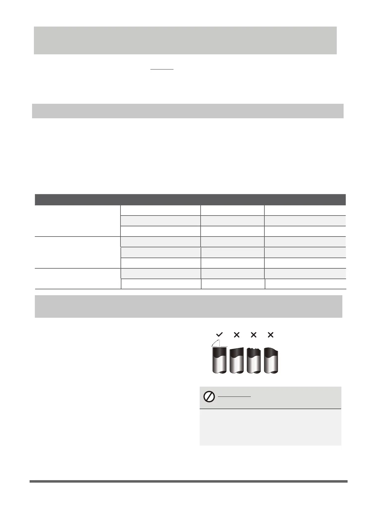
3. Make sure that the pipe is cut at a perfect 90°
angle.
Oblique Rough Warped
90°
DO NOT DEFORM PIPE
WHILE CUTTING
Be extra careful not to damage, dent, or
deform the pipe while cutting. This will
drastically reduce the heating efciency
of the unit.
Maximum Length and Drop Height of Refrigerant Piping per Unit Model
Model Capacity (BTU/h) Max. Length (m) Max. Drop Height (m)
R410A,R32 Inverter Split Air
Conditioner
R22 Fixed-speed
Split Air Conditioner
R410A, R32 Fixed-speed
Split Air Conditioner
< 15,000
< 18,000
25 (82ft) 10 (33ft)
10 (33ft) 5 (16ft)
≥ 15,000 and < 24,000 30 (98.5ft) 20 (66ft)
20 (66ft)
≥ 24,000 and < 36,000 50 (164ft) 25 (82ft)
≥ 21,000 and < 35,000 10(33ft)
≥ 18,000 and < 21,000
≥ 18,000 and < 36,000
15 (49ft)
8(26ft)
8(26ft)< 18,000
20 (66ft)
25 (82ft)
10(33ft)
Refrigerant Piping Connection
Page 32
6.
Place aring tool onto the form.
7.
Turn the handle of the aring tool clockwise
until the pipe is fully ared.
8.
Remove the aring tool and are form, then
inspect the end of the pipe for cracks and
even aring.
Step 4: Connect pipes
When connecting refrigerant pipes, be careful
not to use excessive torque or to deform the
piping in any way. You should first connect the
low-pressure pipe, then the high-pressure pipe.
MINIMUM BEND RADIUS
When bending connective refrigerant piping,
the minimum bending radius is 10cm.
≥10cm (4in)
Radius
Instructions for Connecting Piping to
Indoor Unit
1.
Align the center of the two pipes that you will
connect.
Indoor unit tubing Flare nut Pipe
Max.
Step 2: Remove burrs
Burrs can affect the air-tight seal of refrigerant
piping connection. They must be completely
removed.
1.
Hold the pipe at a downward angle to prevent
burrs from falling into the pipe.
2.
Using a reamer or deburring tool, remove all
burrs from the cut section of the pipe.
Pipe
Reamer
Point down
Step 3: Flare pipe ends
Proper flaring is essential to achieve an airtight
seal.
1.
After removing burrs from cut pipe, seal
the ends with PVC tape to prevent foreign
materials from entering the pipe.
2.
Sheath the pipe with insulating material.
3.
Place are nuts on both ends of pipe. Make
sure they are facing in the right direction,
because you can’t put them on or change
their direction after aring.
Flare nut
Copper pipe
4.
Remove PVC tape from ends of pipe when
ready to perform aring work.
5.
Clamp are form on the end of the pipe.
The end of the pipe must extend beyond the
edge of the are form in accordance with the
dimensions shown in the table below.
PIPING EXTENSION BEYOND FLARE FORM
Outer Diameter of
Pipe (mm)
A (mm)
Min. Max.
Ø 6.35 (Ø 0.25”)
0.7 (0.0275”) 1.3 (0.05”)
Ø 9.52 (Ø 0.375”)
1.0 (0.04”)
1.6 (0.063”)
Ø12.7 (
Ø 0.5”) 1.0 (0.04”) 1.8 (0.07”)
Ø 16 ( Ø 0.63”)
Ø 19 ( Ø 0.75”)
2.0 (0.078”) 2.2 (0.086”)
2.0 (0.078”) 2.4 (0.094”)
Flare form
Pipe
A
 Loading...