Page 26
1. Open and x the position of the panel,
then, open the covers of the two lock
blocks, unscrew the screw , then hold
both sides of the lower panel in the place
marked “PULL”, pull it upwards to release
the buckles, then take the lower panel
down(please refer to Page 22-23).
2.
Open the wire box cover to connect the cable.
First remove the knok-out panel to create a
slot through whick the conduit tube can
install. Then make the cable through the
conduit tube and connect to the indoor unit.
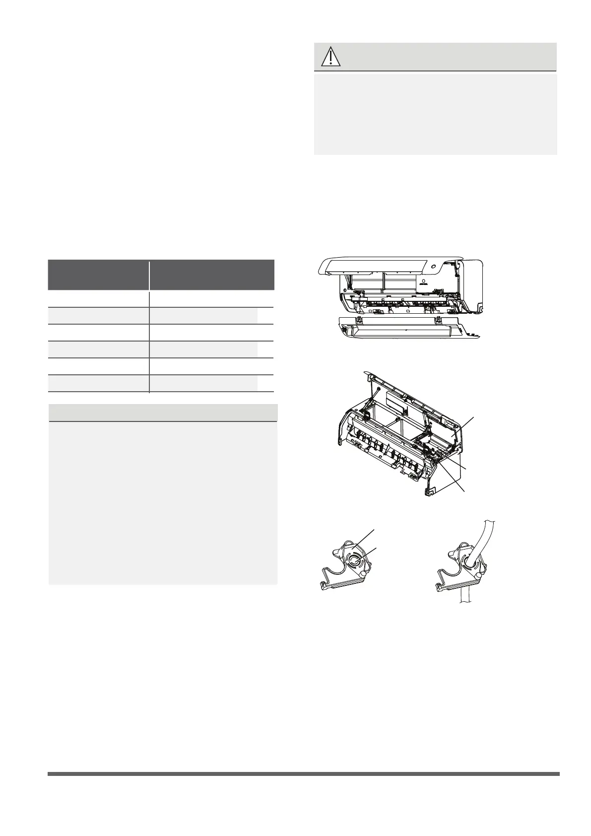
First open the front panel, then remove
the lower panel.
Terminal
block
open the
Wire cover
Rat baffle(some units)
Knock-out
panel
Cable
clamp
NOTE: If the size of the cable is too big, remove
the middle small plastic knock-out panel to create
a slot through which the cable can exit. If you want
to remove the chassis or drain hose, please remove
the rat bafe rst.
WARNING
3.
Unscrew the cable clamp below the terminal
block and place it to the side.
4.
Facing the back of the unit, remove the plastic
panel on the bottom left-hand side.
ALL WIRING MUST BE PERFORMED
STRICTLY IN ACCORDANCE WITH THE
WIRING DIAGRAM LOCATED ON THE
BACK OF THE INDOOR UNIT S FRONT
PANEL .
’
5.
Feed the signal wire through this slot, from
the back of the unit to the front.
6.
Facing the front of the unit, connect the wire
according to the indoor unit’s wiring diagram,
connect the u-lug and rmly screw each wire
to its corresponding terminal.
In North America
Step 6: Connect signal and power cables
The signal cable enables communication between
the indoor and outdoor units. You must first choose
the right cable size before preparing it for connection.
Cable Types
•
Indoor Power Cable
(if applicable):
H05VV-F or H05V2V2-F
•
Outdoor Power Cable: H07RN-F or H05RN-F
•
Signal Cable: H07RN-F
(Not applicable for North America)
NOTE: In North America, choose the cable type
according to the local electrical codes and regulations.
Minimum Cross-Sectional Area of
Power and Signal Cables (For reference)
Rated Current of
Appliance (A)
Nominal Cross-Sectional
Area (mm²)
> 3 and ≤ 6
0.75
> 6 and ≤ 10
1
> 10 and ≤ 16
1.5
> 16 and ≤ 25
2.5
> 25 and ≤ 32
4
> 32 and ≤ 40
6
CHOOSE THE RIGHT CABLE SIZE
The size of the power supply cable, signal
cable, fuse, and switch needed is determined
by the maximum current of the unit. The
maximum current is indicated on the nameplate
located on the side panel of the unit. Refer to
this nameplate to choose the right cable, fuse,
or switch.
NOTE: In North America, please choose the
right cable size according to the Minimum
Circuit Ampacity indicated on the nameplate
of the unit.
Page 26
CAUTION
DO NOT MIX UP LIVE AND NULL WIRES
This is dangerous, and can cause the air
conditioning unit to malfunction.
7.
After checking to make sure every connection
is secure, use the cable clamp to fasten the
signal cable to the unit. Screw the cable clamp
down tightly.
8 .
Replace the wire cover on the front of the
unit, and the plastic panel on the back.
DRAIN HOSE MUST BE ON BOTTOM
Make sure that the drain hose is at the bottom
of the bundle. Putting the drain hose at the
top of the bundle can cause the drain pan
to overflow, which can lead to fire or water
damage.
DO NOT INTERTWINE SIGNAL CABLE WITH
OTHER WIRES
While bundling these items together, do not
intertwine or cross the signal cable with any
other wiring.
2.
Using adhesive vinyl tape, attach the drain
hose to the underside of the refrigerant pipes.
3.
Using insulation tape, wrap the signal wire,
refrigerant pipes, and drain hose tightly
together. Double-check that all items are
bundled.
DO NOT WRAP ENDS OF PIPING
When wrapping the bundle, keep the ends
of the piping unwrapped. You need to access
them to test for leaks at the end of the
installation process (refer to Electrical Checks
and Leak Checks section of this manual)
NOTE ABOUT WIRING
THE WIRING CONNECTION PROCESS MAY
DIFFER SLIGHTLY BETWEEN UNITS AND
REGIONS.
Before passing the piping, drain hose, and the
signal cable through the wall hole, you must
bundle them together to save space, protect
them, and insulate them(This may not applicable
for some locations in US).
1.
Bundle the drain hose, refrigerant pipes, and
signal cable as shown below:
Indoor Unit
Space behind unit
Refrigerant piping
Drain hose
Signal wire
Insulation tape
Step 7: Wrappping and cables
Step 8: Mount indoor unit
If you installed new connective piping
to the outdoor unit, do the following:
1.
If you have already passed the refrigerant
piping through the hole in the wall, proceed
to Step 4.
2.
Otherwise, double-check that the ends of the
refrigerant pipes are sealed to prevent dirt or
foreign materials from entering the pipes.
3.
Slowly pass the wrapped bundle of refrigerant
pipes, drain hose, and signal wire through the
hole in the wall.
4.
Hook the top of the indoor unit on the upper
hook of the mounting plate.
5.
Check that unit is hooked rmly on mounting
by applying slight pressure to the left and
right-hand sides of the unit. The unit should
not jiggle or shift.
6.
Using even pressure, push down on the
bottom half of the unit. Keep pushing down
until the unit snaps onto the hooks along the
bottom of the mounting plate.
7.
Again, check that the unit is firmly mounted
by applying slight pressure to the left and the
right-hand sides of the unit.
 Loading...