Version 1.00 | Optidrive CoolVert User Guide | 25www.invertekdrives.com
4
Set-up and Operation
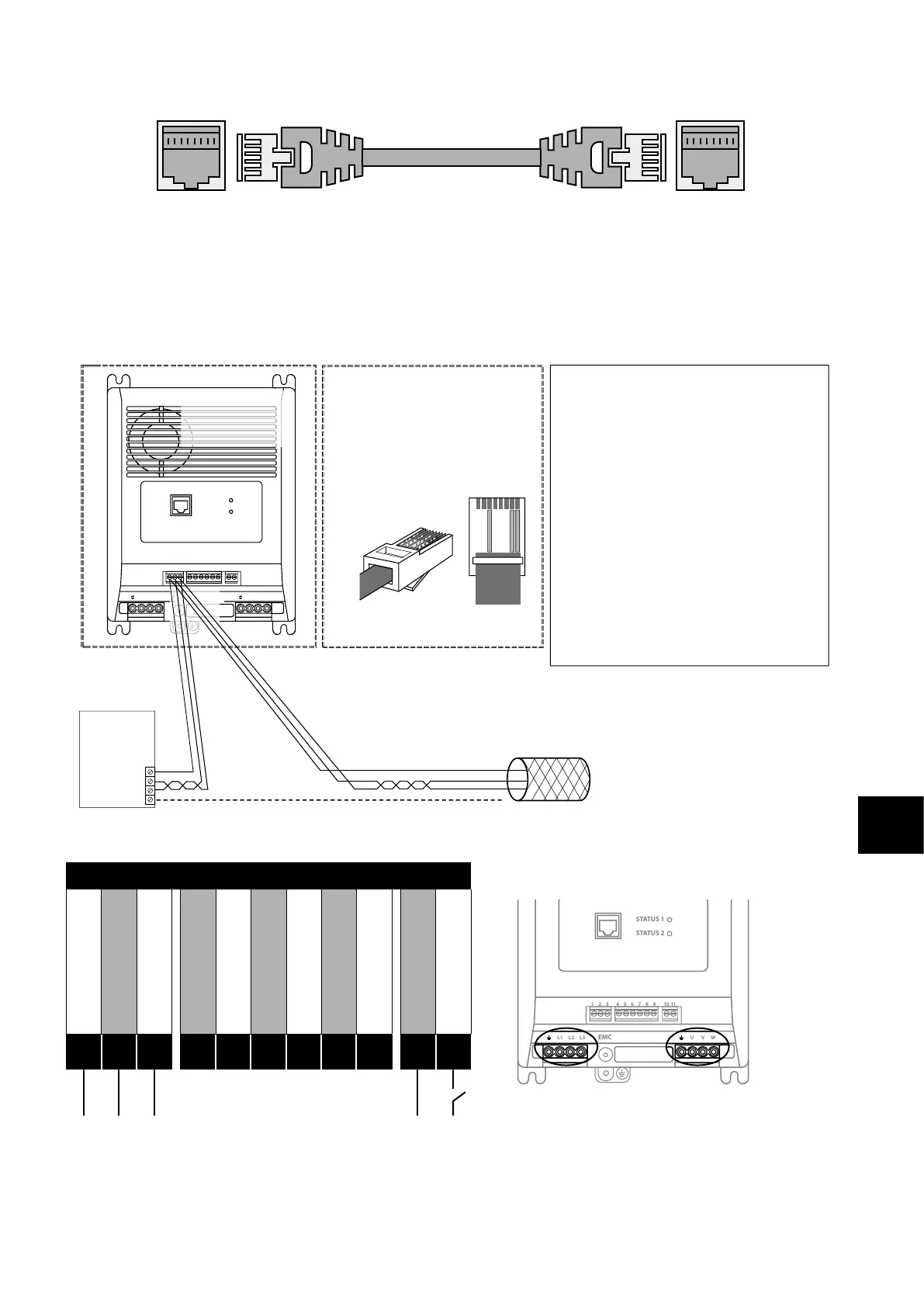
Master RJ45 Slave RJ45
STO signal must be provided in order to permit running the motor. Run enable is provided by the Digital Input with the Start/Stop
command coming from the master drive. Speed reference also comes from the master drive. The slave drive must be connected to the
master drive by a straight through (no crossover) RJ45 patch lead.
4.2.2. RS-485 Communications Electrical Connections
The Optidrive Coolvert has two separate points where you can access the Modbus RTU communications. The Modbus RTU
connection can be made via the RJ45 connector or control terminals 1, 2 & 3. As shown below:
1 2 3 4 5 6 7 8 9
10
11
STATUS 1
STATUS 2
L1 L2 L3 U V W
EMC
Modbus RTU
RS485Controller
RS485+
RS485-
0Volt / Common
Ground
NOTES
• Use 3 or 4 Conductor Twisted Pair Cable
•RS485+ and RS485- must be twisted pair
• Ensure the network taps for the drive
are kept as short as possible
• Network terminating resistor (120R) may
be used at the end of the network to
reduce noise
RS485+
RS485-
0Volt / Common
Shield
12 3
RS485+
0Volt / Common
Connection to
the drive through
the terminals
RS485-
Pin3–0 Volt / Common
Pin7–RS485- (Modbus RTU)
Pin8–RS485+ (Modbus RTU)
RJ45 connector pinout
Direct connection to the drive
through the built-in RJ45 port
1 2 3 4 5 6 7 8
1
2
3
4
5
6
7
8
•Terminate the network cable shield at
the controller only. Do not terminate at
the drive!
•0 Volt common must be connected
across all devices and to reference0 Volt
terminal at the controller
•Do not connect the 0V Common of the
network to power ground
4.2.3. RS-485 Communications Electrical Connections via Control Terminals
Serial Communication Connection
1 2 3 4 5 6 7 8 9
10
11
STATUS 1
STATUS 2
L1 L2 L3 U V WEMC
1 2 3 4 5 6 7 8 9
10
11
STATUS 1
STATUS 2
L1 L2 L3 U V WEMC
1 2 3 4 5 6 7 8 9
10
11
STATUS 1
STATUS 2
L1 L2 L3 U V WEMC
0V Common
Modbus TX/RX +
Modbus TX/RX -
+24V Output (100mA)
Digital Input 1
Analogue Input 1
0V Common
STO +
STO -
User Relay A
User Relay B
1
2
3
4
5
6
7
8
9
10
11