14
Micro-breaker should be installed between inverter and grid, any load should not be
connected with inverter directly.
Step1. Check the grid voltage.
1.1 Check the grid voltage and compare with the permissive voltage range (Please refer
to technical data).
1.2 Disconnect the circuit board from all the phases and secure against re-connection.
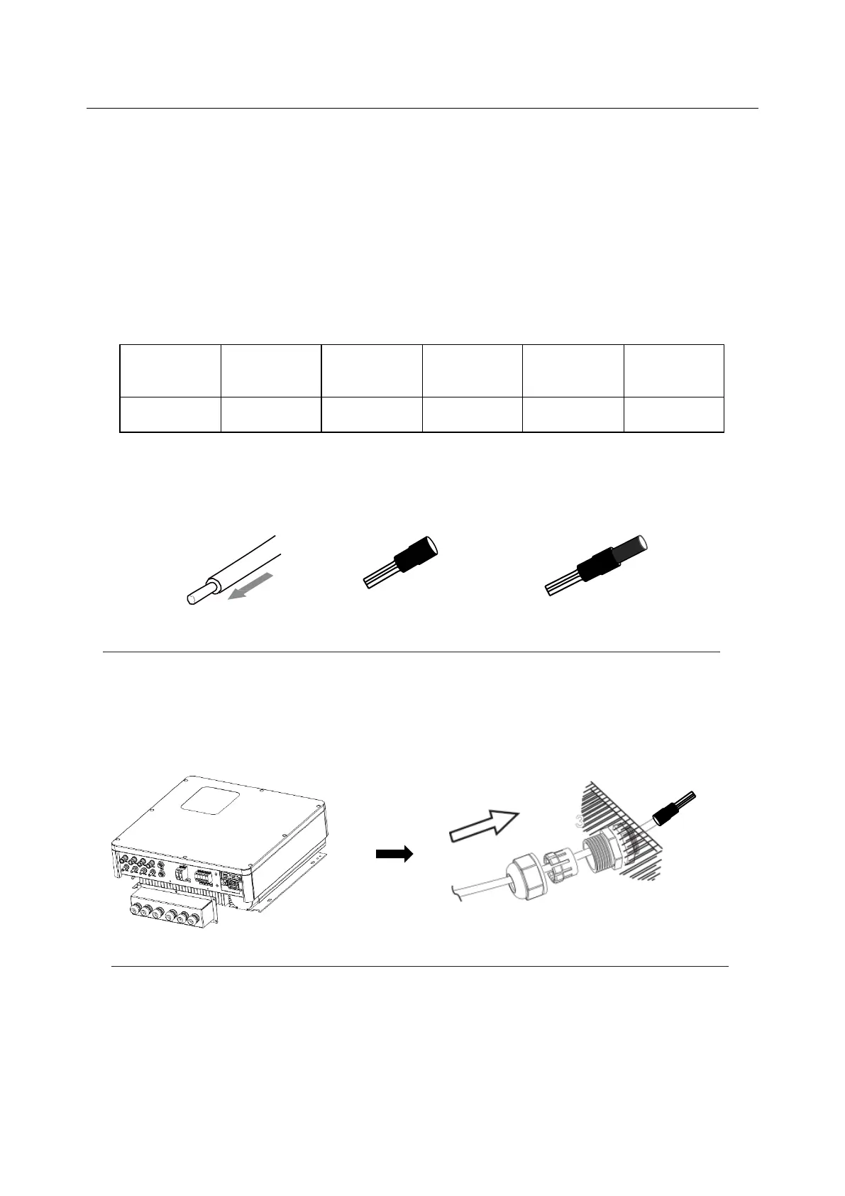
Step2.Grid cables choose
Use the right pin terminal from the accessory box. Press the connectors on cable
conductor core tightly.
Step3. Choose the wire to connect with the cold-pressed terminal.
(Remove 18mm of insulation from the end of wire.)
Step4. Cross the Grid cables through the grid port, connect Grid cables to Grid terminals.
 Loading...