13
1.1 Use multi meter to measure module array voltage.
1.2 Check the PV+ and PV- from the PV string combiner box correctly.
1.3 Please make sure the impedance between the positive pole and negative pole of PV
to earth should be MΩ level.
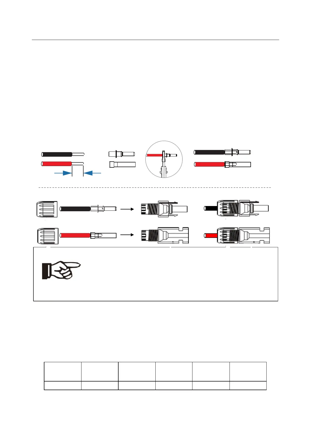
Step 2: Separating the PV connector.
1. Wiring.
1.1 Choose the 12 AWG wire to connect with the cold-pressed terminal.
1.2 Remove 12mm of insulation from the end of wire.
1.3 Insert the insulation into pin contact and use crimping plier to clamp it.
1.4 Insert pin contact through the cable nut to assemble into back of the male or female
plug. When you feel or heard a “click” sound the pin contact assembly is seated correctl.
1.5 Plug the PV conntector into the corresponding PV connector on inverter.
Note!
The following requirements of PV modules need to be applied for
each input area;
Please do not make PV positive or negative ground!
In order to save cable and reduce the DC loss, we suggest to install the
inverter near PV modules.
5.2 Grid Connection
Hybrid series inverter are designed for single phase grid. Voltage is
230V, frequency is 50Hz.
Other technical requests should comply
with the requirement of the local public grid.
 Loading...