EasyManuals Logo
Home>INVT>Inverter>BD-RH1 Series

INVT BD-RH1 Series User Manual

INVT BD-RH1 Series
23 pages
To Next Page IconTo Next Page
To Previous Page IconTo Previous Page
Page #18 background imageLoading...
Page #18 background image
18
5.5 Interface definition
This chapter introduces the definition of hybrid inverter's external interface and cable
manufacturing.
BMS (RJ45 PIN) Denition
Communication interface between inverter and battery is RS485 or CAN with RS485
connector.
PIN
1
2
3
4
5
6
7
8
CAN
Definition
X
X
X
BMS_CANH
BMS_CANL
X
X
X
RS485
Definition
X
X
X
X
X
GND
BMS_485A
BMS_485B
When using RS485 protocol, please note that PIN2 must be disconnected.
Note
The battery communication can only work when the battery BMS is compatible with
the inverter.
Dry_IO (RJ45 PIN) Definition
1
2
3
4
5
6
7
8
DRYO_1A
DRYO_1B
X
DRYI_1
DRYI_1B
X
X
X
Dry contact short
X
Dry contact
Input
+5V
X
X
X
Please refer to BMS connection for Meter connection. Please kindly note the PIN
definition and port position will be slightly different.
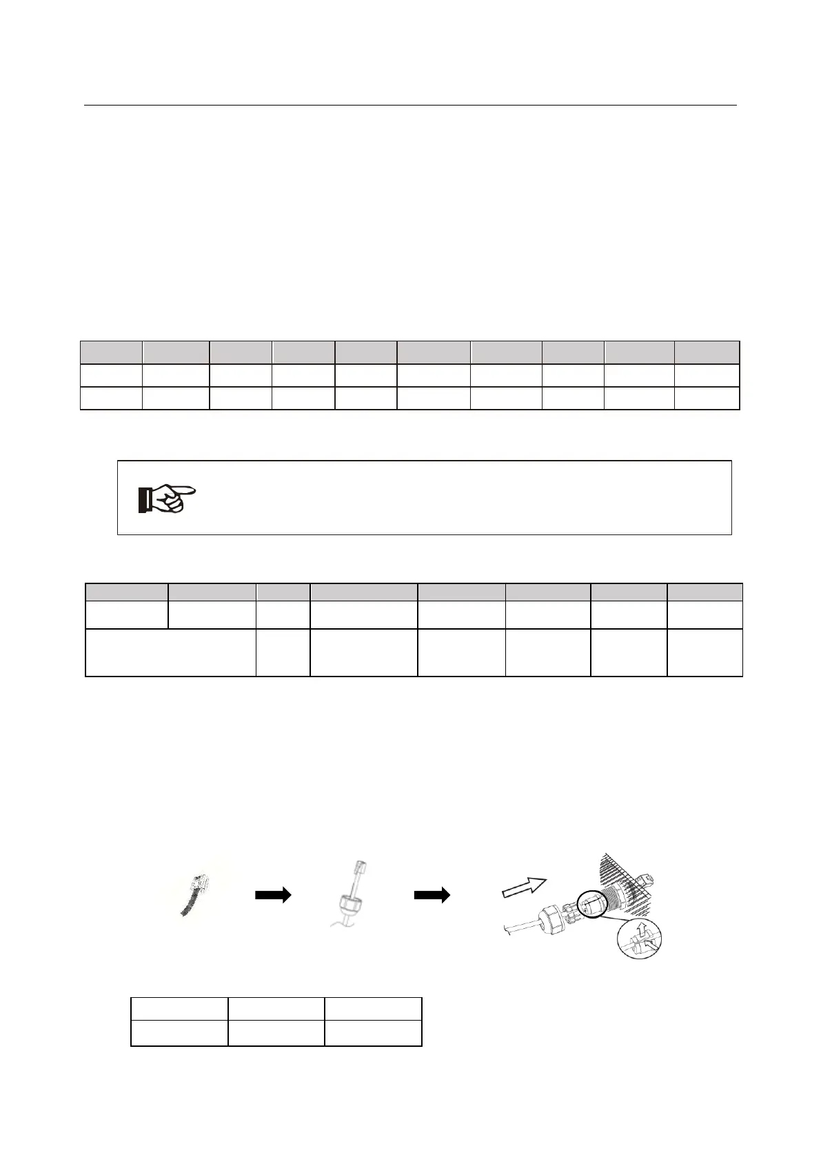
Step1. Make RS485 wire, Cross the Meter wire through the com port
Step2. Insert one RJ45 side of the cable into Meter port inside of inverter and the
other side into BMS-485port of the meter.
DRM
CT
Dry IO
BMS
Power CAN
NTC

Questions and Answers:

Question and Answer IconNeed help?

Do you have a question about the INVT BD-RH1 Series and is the answer not in the manual?

INVT BD-RH1 Series Specifications

General IconGeneral
BrandINVT
ModelBD-RH1 Series
CategoryInverter
LanguageEnglish

Related product manuals