Connection Steps:
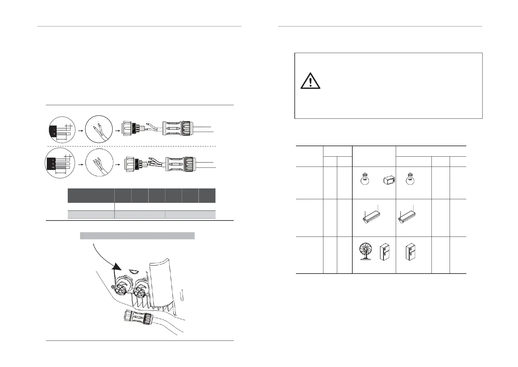
Step1.Make EPS wires.
1. Choose the appropriate wire(cable size: refer to picture below).
2. Reserve about 60mm of conductor material sectional area.
3. Remove 10mm of insulation from the end of wire.
4. Separate the docking screw cap of the AC terminal from the housing portion.
5. Insert stripped wires into AC terminal and tighten the screws with a hexagonal wrench.
6. Tighten the docking screw cap and housing portion of the AC terminal.
Step2. Connect the AC connector to the EPS port of the inverter and tighten
the screw cap .
Step2
.
Requirements for EPS load
WARNING!
Make sure the EPS load power rating is withinEPS output
rating, otherwise the inverter will shutdown with an "over
load" warning.
When an "over load" is appeared, adjust the load power to
make sure it is within the EPS output power range, then
turn the inverter back on.
For the nonlinear load, please make sure the inrush power
should be within the EPS output power range.
Below table shows some common feasible loads for you reference.
Type
Power
Common
equipment
Example
Equipment
Resistiv
e load
R 1
R 1
TV
lamp
100W
Incandescent
lamp
(W)
(W)
Capacitiv
e load
R 2
R
Fluorescent lamp
40W
80VA
(W)
(W)
Inductiv
e load
3~
R 2
Fan
Fridge
150W
Fridge
-
(W)
(W)
Electrical Connection Electrical Connection
Table 5 Cable and Micro-breaker recommended
Model
-RL1
-RL1
-RL1
-RL1
-RL1
-RL1
EPS Cable
≥ 5mm²
EPS breaker
25A
32A
Note: Connect the AC connector to the EPS
EPS
GRID
60mm
12mm
60mm
12mm
I
Version
Step1
.
E
Version
28 29