Model
-RL1
-RL1
-RL1
-RL1
-RL1
-RL1
Voltage
Nominal voltage of DC breaker should be
larger than maximum voltage of
battery.
Current[A]
160A
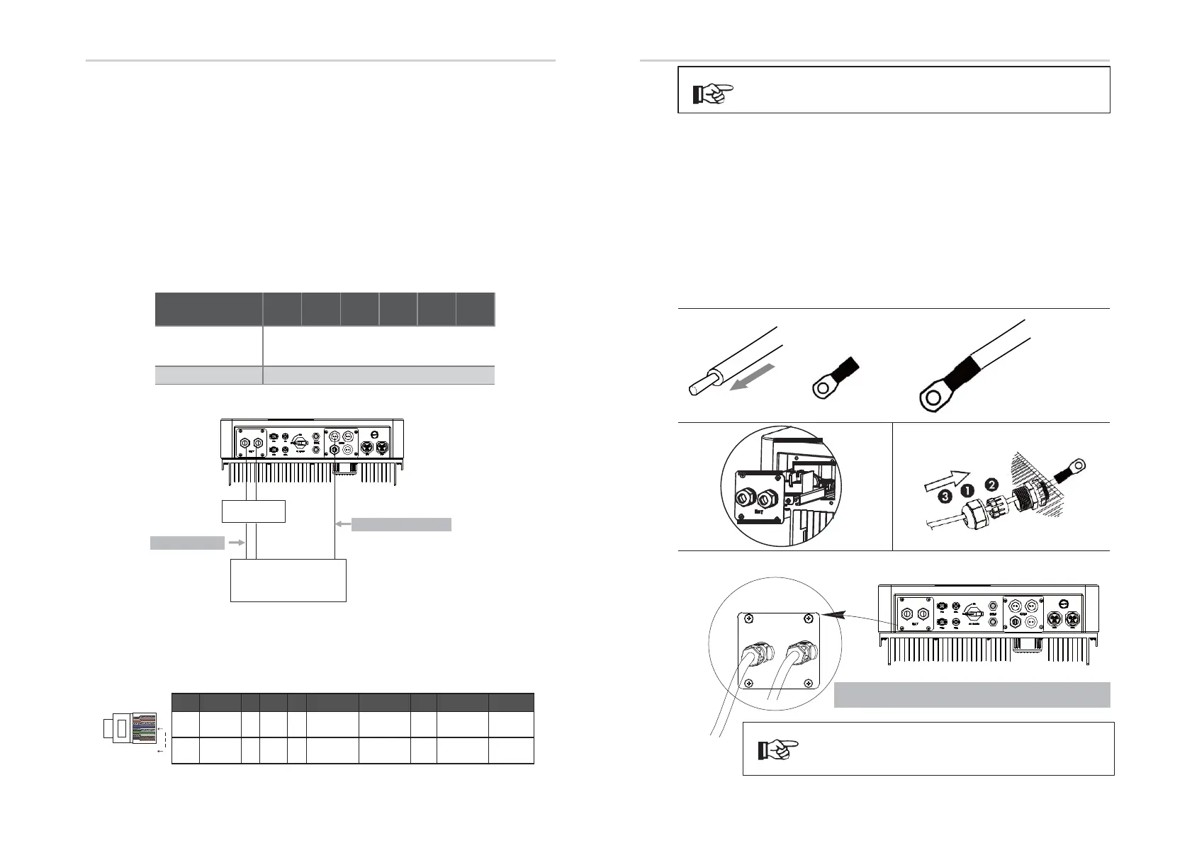
6.4 Battery
Connection
Charging & discharging system of BD series inverter is designed for
high-voltage lithium battery.
Before choosing battery, please note the maximum voltage of battery
can not
exceed 59V and the rated voltage of battery can not exceed 48V,
and the battery communication should be compatible with BD Hybrid
inverter.
Battery breaker
Before connecting to battery, please install a nonpolarized DC breaker to
make sure inverter can be securely disconnected during maintanance.
Battery connection
diagram
Power Connection Steps:
Step1. Choose the 2 AWG wire and strip the cable to 15mm.
Step2. Select two O-terminals with an aperture of M6.
Step3. Insert the stripping line into the O-terminal and clamp it with a crimping
clamp. Step4. Remove waterproof cover plate.
Step5. Disassemble the waterproof connector and pass the cable through
the waterproof connector.
S. tep6. Connect the cable to the terminal of the inverter .
.Step7. Assemble waterproof connectors and waterproof covers plate.
+
CAN/ RS485
Nonpolarized
DC breaker
Power connection
48V lithium battery
Note: When working with Pylontech batteries, It is recommended the number of battery
module (H48050-15S) is 2-7 and the number of battery manager system (SC0500A-100S) is 1.
Communication connection
BMS PIN Definition
Communication interface bewteen inverter and battery is RS485 or CAN
with a RJ45 connector.
Note!
The battery communication can only work when the battery
BMS is compatible with the inverter.
1
8
Electrical Connection Electrical Connection
Step1,2,
3.
Step4
.
Step5
.
Step6,7.
PIN
2
3
4
5
6 7 8
fi
on
X
X
BMS_CANH
BMS_CANL
X
X X
fi
on
X X
X X GND
BMS_485A
When using RS485 protocol, please note that PIN2 must be disconnected.
BAT
Note: BAT port, not PV port!The positive pole on the left and
the negative pole on the right.
Note!
Positive and negative lines are not allowed to
reverse.
30
31