Detailed Function Description
41
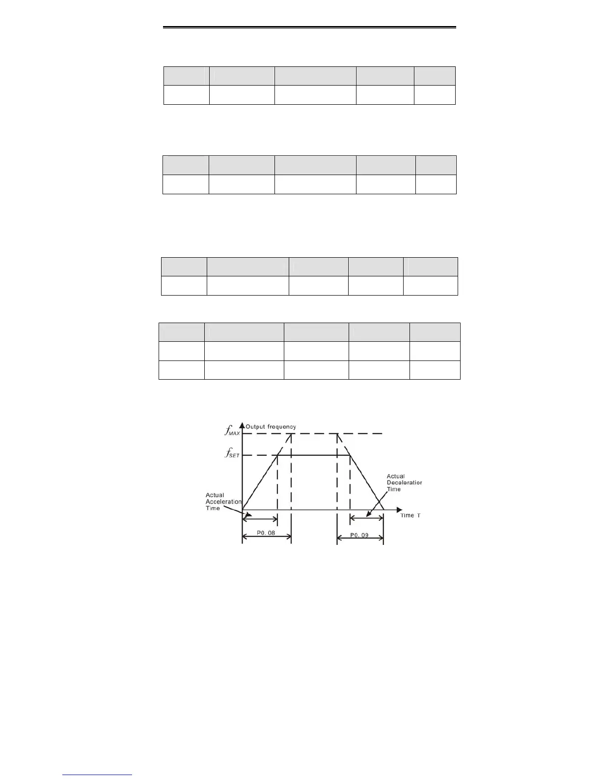
z Actual acceleration time and deceleration time are determined by maximum
frequency. Please refer to description of P0.08 and P0.09.
Function
Code
Name Description Setting Range
Factory
Setting
P0.05
Upper frequency
limit
P0.06~ P0.04 P0.06~P0.04 50.00Hz
Notice:
z Upper frequency limit should not be greater than the maximum frequency
(P0.04).
z Output frequency should not exceed upper frequency limit.
Function
Code
Name Description Setting Range
Factory
Setting
P0.06
Lower frequency
limit
0.00 Hz ~ P0.05 0.00~P0.05 0.00Hz
Notice:
z Lower frequency limit should not be greater than upper frequency limit
(P0.05).
z If frequency reference is lower than P0.06, the action of inverter is determined
by P1.12. Please refer to description of P1.12.
Function
Code
Name Description
Setting
Range
Factory
Setting
P0.07
Keypad reference
frequency
0.00 Hz ~
P0.04
0.00~P0.04 50.00Hz
When P0.03 is set to be 0, this parameter is the initial value of inverter reference
frequency
Function
Code
Name Description Setting Range
Factory
Setting
P0.08 Acceleration time 0 0.0~3600.0s 0.0~3600.0
Depend on
model
P0.09 Deceleration time 0 0.0~3600.0s 0.0~3600.0
Depend on
model
Acceleration time is the time of accelerating from 0Hz to maximum frequency (P0.04).
Deceleration time is the time of decelerating from maximum frequency (P0.04) to 0Hz.
Please refer to following figure.
 Loading...
