Detailed Function Description
74
This parameter is normally used when rated power of inverter is greater than
rated power of motor.
Motor overload protection time: 60s with 200% of rated current. For details,
please refer to above figure.
Function
Code
Name Description Setting Range
Factory
Setting
PB.02
Threshold of
trip-free
70.0~110.0% 70.0~110.0 80.0%
PB.03
Decrease rate
of trip-free
0.00Hz~P0.04 0.00Hz~P0.04 0.00Hz
If PB.03 is set to be 0, the trip-free function is invalid.
Trip-free function enables the inverter to perform low-voltage compensation when DC bus
voltage drops below PB.02. The inverter can continue to run without tripping by reducing
its output frequency and feedback energy via motor.
Notice: If PB.03 is too big, the feedback energy of motor will be too large and may
cause over-voltage fault. If PB.03 is too small, the feedback energy of motor will be
too small to achieve voltage compensation effect. So please set PB.03 according to
load inertia and the actual load.
Function
Code
Name Description
Setting
Range
Factory
Setting
PB.04
Over-voltage
stall protection
0: Disabled
1: Enabled
0~1 1
PB.05
Over-voltage
stall protection
point
110~150% 110~150
380V:130%
220V:120%
During deceleration, the motor’s decelerating rate may be lower than that of inverter’s
output frequency due to the load inertia. At this time, the motor will feed the energy back
to the inverter, resulting in DC bus voltage rise. If no measures taken, the inverter will trip
due to over voltage.
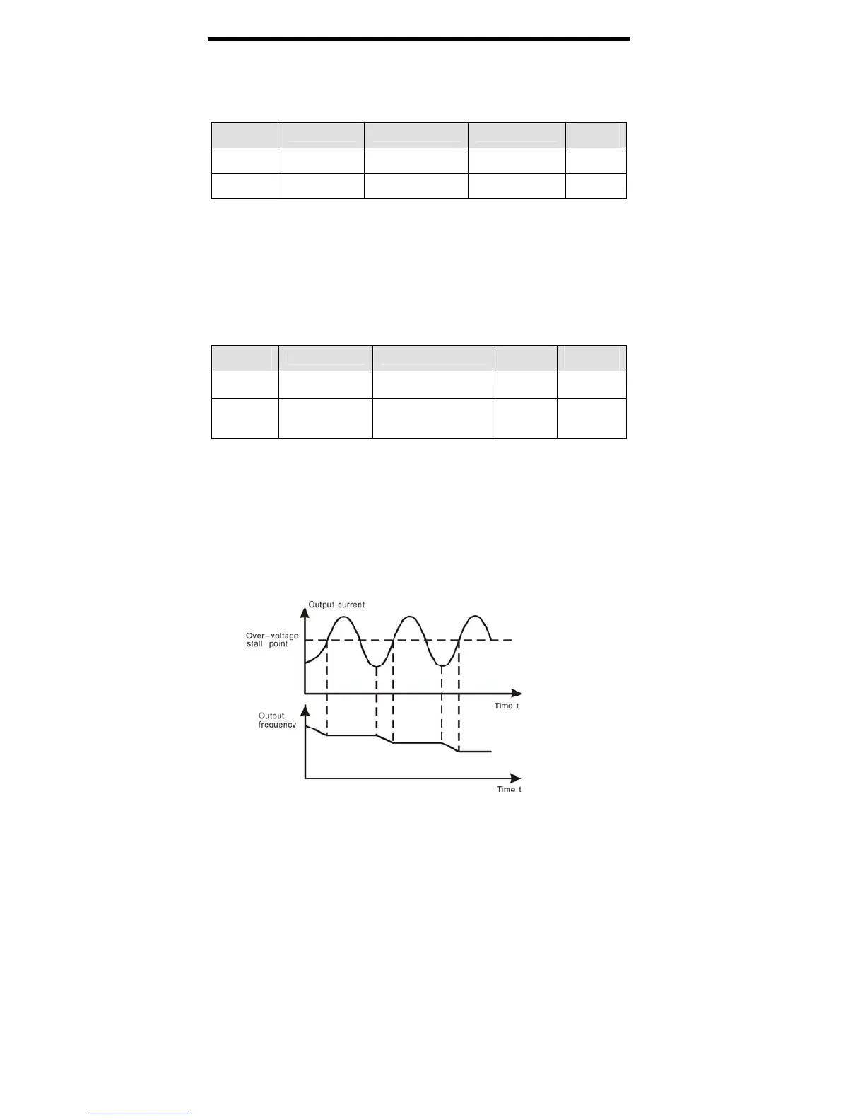
During deceleration, the inverter detects DC bus voltage and compares it with
over-voltage stall protection point. If DC bus voltage exceeds PB.05, the inverter will stop
reducing its output frequency. When DC bus voltage become lower than PB.05, the
deceleration continues, as shown in following figure.
 Loading...
