Goodrive350-19 series VFD Operating
- 191 -
and at this point, the pulse string acts as frequency source, P21.13 (position feedforward gain) should
be set to 100%, and the speed acceleration/deceleration time is determined by the acceleration
/deceleration time of pulse string, the pulse string acceleration/deceleration time of the system can be
adjusted. If the pulse string acts as the frequency source in speed control, you can also set P21.00 to
0000, and set the frequency source reference P00.06 or P00.07 to 12 (set by pulse string AB), at this
point, the acceleration/deceleration time is determined by the acceleration/deceleration time of the
VFD, meanwhile, the parameters of pulse string AB is still set by P21 group. In speed mode, the filter
time of pulse string AB is determined by P21.29.
Step 8: The input frequency of pulse string is the Same as the feedback frequency of encoder pulse,
the relation between them can be changed by altering P21.11 (numerator of position command ratio)
and P21.12 (denominator of position command ratio)
Step 9: When running command or servo enabling is valid (by setting P21.00 or terminal function 63),
it will enter pulse string servo running mode.
4. Commissioning procedures for spindle positioning
Spindle orientation is to realize orientation functions like zeroing and division based on closed-loop
vector control
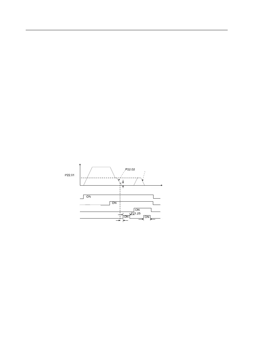
Frequency
Deceleration time of spindle orientation
Speed of
accurate-stop
of spindle
Time
P21.09 Completion
range of positioning
Running command
Zeroing command
Zeroing selection terminal 1
Positioning completion signal
Hold time of positioning completion signal
P21.10 Detection time
for positioning completion
P21.25 Hold time of positioning completion signal
Step 1–4: These four steps are the Same as the first four steps of the commissioning procedures for
closed-loop vector control, which aim to fulfill the control requirements of closed-loop vector control,
thus realizing spindle positioning function in either position control or speed control mode.
Step 5: Set P22.00.bit0=1 to enable spindle positioning, set P22.00.bit1 to select spindle zero input. If
the system adopts encoder for speed measurement, set P22.00.bit1 to 0 to select Z pulse input; if the
system adopts photoelectric switch for speed measurement, set P22.00.bit1 to 1 to select
photoelectric switch as zero input; set P22.00.bit2 to select zero search mode, set P22.00.bit3 to
enable or disable zero calibration, and select zero calibration mode by setting P22.00.bit7.
Step 6: Spindle zeroing operation
a) Select the positioning direction by setting P22.00.bit4;
b) There are four zero positions in P22 group, you can choose one out of four zeroing positions

 Loading...

