iMars grid-tied solar inverters Display panel
41
The operation state and parameters can be attained from the LED indicators and LCD display. The
displayed content and parameters can also be set or modified by the operation panel.
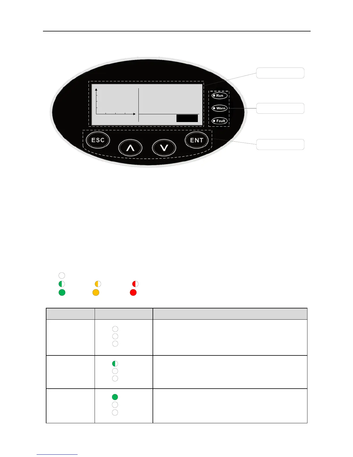
Figure 6.1 Operation panel
6.1 LED indicators
There are three LED indicators on the panel:
(1) “Run”, operation indicator, green;
(2) “Warn” recoverable fault indicator, yellow;
(3) “Fault”, unrecoverable fault indicator, red.
The inverter state includes 6 states of stand-by, self-inspection, power generation, recoverable
fault and unrecoverable fault; LED indicators are on, off and blinking. Please refer to table 6-1 for
detailed state of inverter and LED indicators state.
“ ”: LED indicator is off;
“ ” (green), “ ” (yellow), “ ” (red): LED indicator is blinking at every 0.25S or 0.5S;
“ (Green), “ ” (yellow), “ ” (red): LED indicator is on.
Table 6-1 Inverter state and LED indicators
Green indicator blinks in every 0.25s, others off.
Power on and ready for self-inspection
Green indicator keeps on, others off.
Grid-tied power generation.