iMars grid-tied solar inverters Display panel
43
communication address, password and factory defaults.
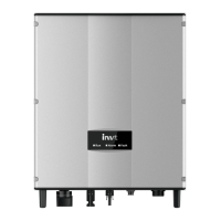
Figure 6.2 Main interface
The main interface of the LCD screen is shown as the figure above:
(1) The curve displays the power changing at the current day;
(2) The words on the screen display the current key parameters of the inverter. Three lines of
words are displayed at a time, but if the inverter is in operation or stand-by state, the words
are rolling forward at every 3s. And the user can press “ ” or “ ” to look up the
information freely;
(3) 5 states of the inverter are displayed on the screen;
(4) If the inverter is in fault or warning state, up to 8 corresponding fault codes can be
displaying on the screen.
6.4 Functions operation
Most of the parameters can be viewed and set through the LCD screen and operation panel.
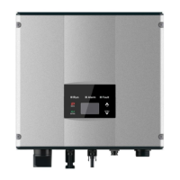
Figure 6.3 Main interface
6.4.1 Monitoring parameters
Press “ ” and “ ” in the main interface to select “Monit Param”, and then press “ENT” to view
the parameters which is shown in figure 6.4. Go the front or next page through “ ” and “ ” and
return through “ESC”.
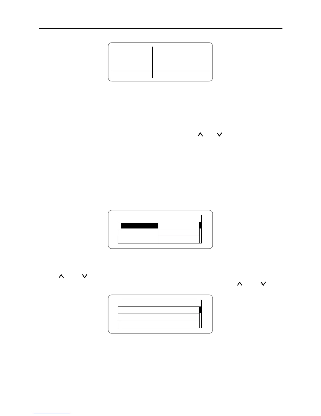
Figure 6.4 Monitoring parameters
Different inverter has different parameters. “●” in table 6-2 means the monitoring parameters of
the inverter can be displayed on the LCD screen.