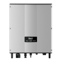
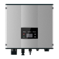
Figure 7.2 RS485 pin on inverter Figure 7.3 Communication connector
Connection steps:
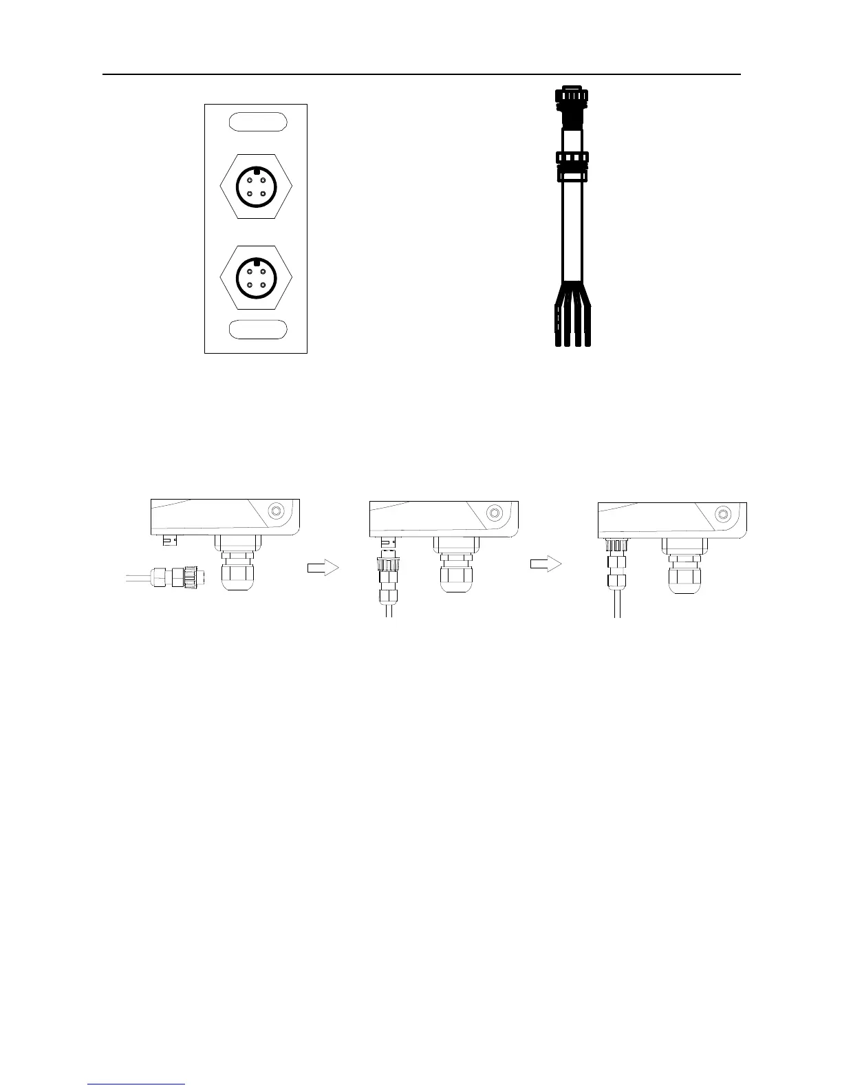
(1) Connect the communication connector configured for the inverter to the RS485 terminal of
the inverter, as shown in Fig 7.4;
(2) According to Table 7-1, connect the communication connector pinout and the user's
device, make sure the connection is correct.
Figure 7.4 Communication cable connection
(3) Please download the monitoring software “iMars WinExpert” and its operation instruction
on website.
7.2 Optional communication
The optional communication modes include Ethernet, WiFi, GPRS and ENET,which also need
corresponding communication parts and components as shown in Table 7-2.All operation
parameters of the inverter are output from port “RS485-M” to the communication devices, finally
transmitted to the monitoring system as standard Ethernet and WIFI signal. See Figure 7.1.