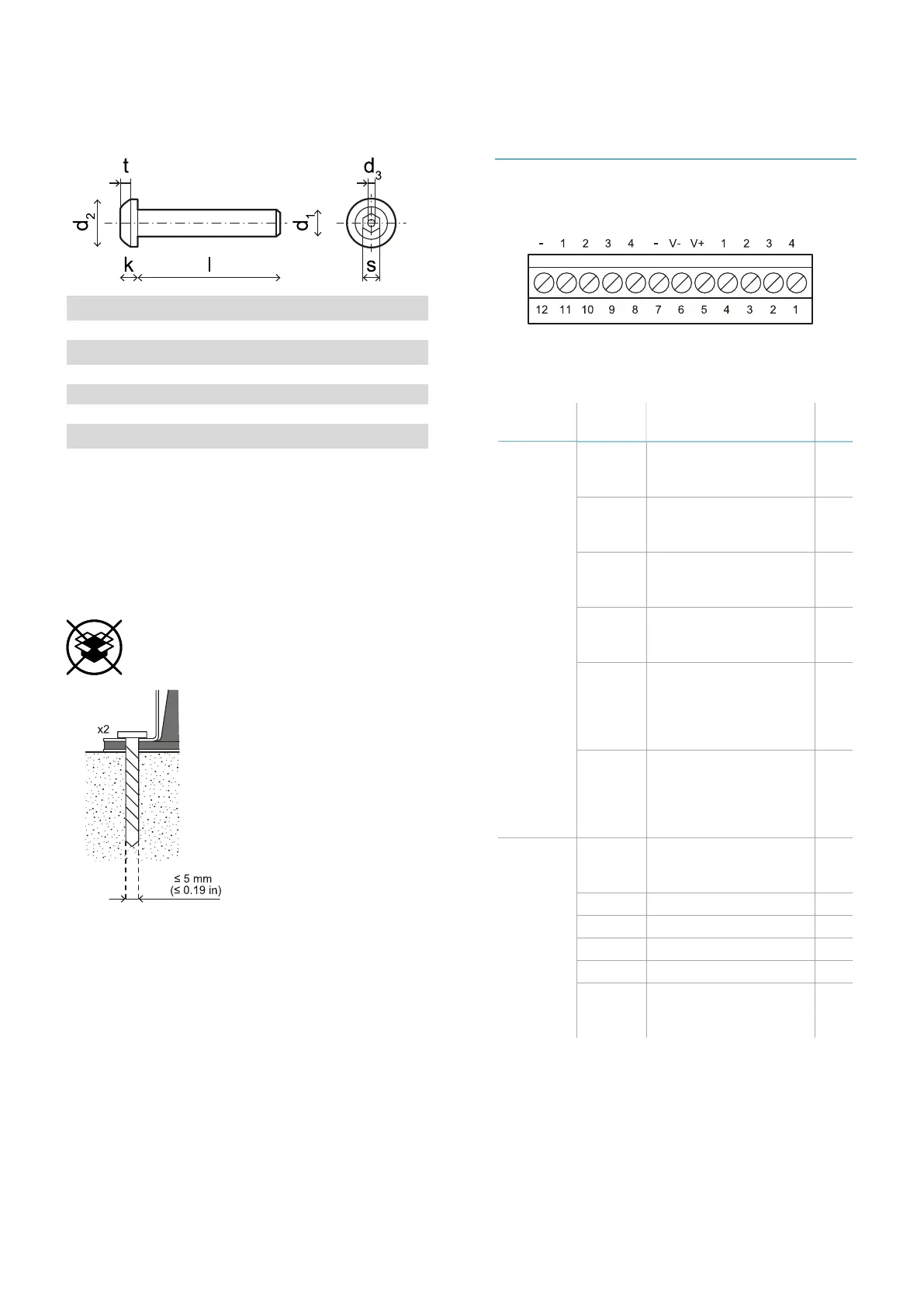
8.1.7 Side screw specifications
Pin Hex button head security screw
d
1
M4
l 10 mm (0.39 in)
d
2
7.6 mm (0.30 in)
k 2.2 mm (0.09 in)
t min 1.3 mm (0.05 in)
s 2.5 mm (0.10 in)
d
3
max 1.1 mm (0.04 in)
8.1.8 Bottom screws
specifications
The bottom screws can be:
l cheese head
l button head
Note: Avoid using countersunk head screws.
8.2 Terminal blocks and
connector pin-outs
8.2.1 Digital inputs and outputs
terminal block
Note: facing the control unit so that the terminal
block is on the top left, number 12 is the closest to
the control unit corner.
Terminal
block
Symbol Description Pin
Digital In 4 Input 2, Channel 2, 24
V dc type 3 - INPUT
#2-2
1
3 Input 2, Channel 1, 24
V dc type 3 - INPUT
#2-1
2
2 Input 1, Channel 2, 24
V dc type 3 - INPUT
#1-2
3
1 Input 1, Channel 1, 24
V dc type 3 - INPUT
#1-1
4
V+ V+ (SNS), 24 V dc for
diagnostics of the
digital inputs
(mandatory if at least
one input is used)
5
V- V- (SNS), common
reference for all digital
inputs (mandatory if at
least one input is
used)
6
Digital
Out
- GND, common
reference for all digital
outputs
7
4 Output 4 (OSSD4) 8
3 Output 3 (OSSD3) 9
2 Output 2 (OSSD2) 10
1 Output 1 (OSSD1) 11
- GND, common
reference for all digital
outputs
12
Note: the cables used must have a maximum length
of 30 m (98.4 ft) and the maximum operating
temperature must be at least 80 °C.
Note: use only copper wires with a minimum gauge
of 18 AWG and a torque of 0.62 Nm (5,5 lbs in).
8. Technical references
LBK System Series| Instruction manual v1.2 SET 2021|SAF-UM-LBKBus-en-v1.2|© 2020-2021 Inxpect SpA
89