9
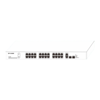
2. Connecting devices to the switch’s RJ45 ports
Connect each PC to an RJ45 port on the switch’s front panel (Figure 7) with an Ethernet cable.
Figure 7: Connect PC to Switch’s RJ45 Port
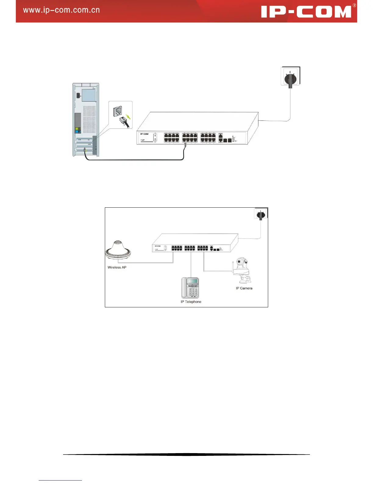
3. Connect PDs
Connect PDs (PoE powered devices, for example, 802.3at-/802.3af-compliant AP, IP telephone or IP camera) to the
switch. Power is transmitted on conductors: 1, 2, 3 and 6.
Figure 8: Connect PDs to Switch