8
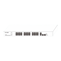
2). Attach the supplied mounting brackets to the side of the switch.
3). Insert the screws provided in the rack-mount kit through each bracket and into the bracket mounting holes in the
switch.
4). Align the mounting holes in the brackets with the holes in the rack.
5). Tighten the screws with a screwdriver to secure each bracket.
Figure 5 Install Switch in a 19-inch Rack
Note:
Always install devices from the bottom of the rack to the top. This will prevent the rack from over balancing and
toppling over.
2.3 Hardware Connection
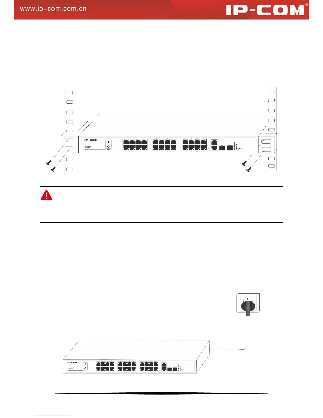
1. Applying AC Power
Make sure power source meets switch power specification: AC 100-240V 50/60Hz 6A.
a). Connect the female end of the supplied AC power adapter cable to the power receptacle on the back of the
switch.
b). Connect the 3-pronged end of the AC power adapter cable to the 3-pronged AC source.
Figure 6: Connect Switch to Power Source