5
Status LEDs
RESET button
PoE-MAX
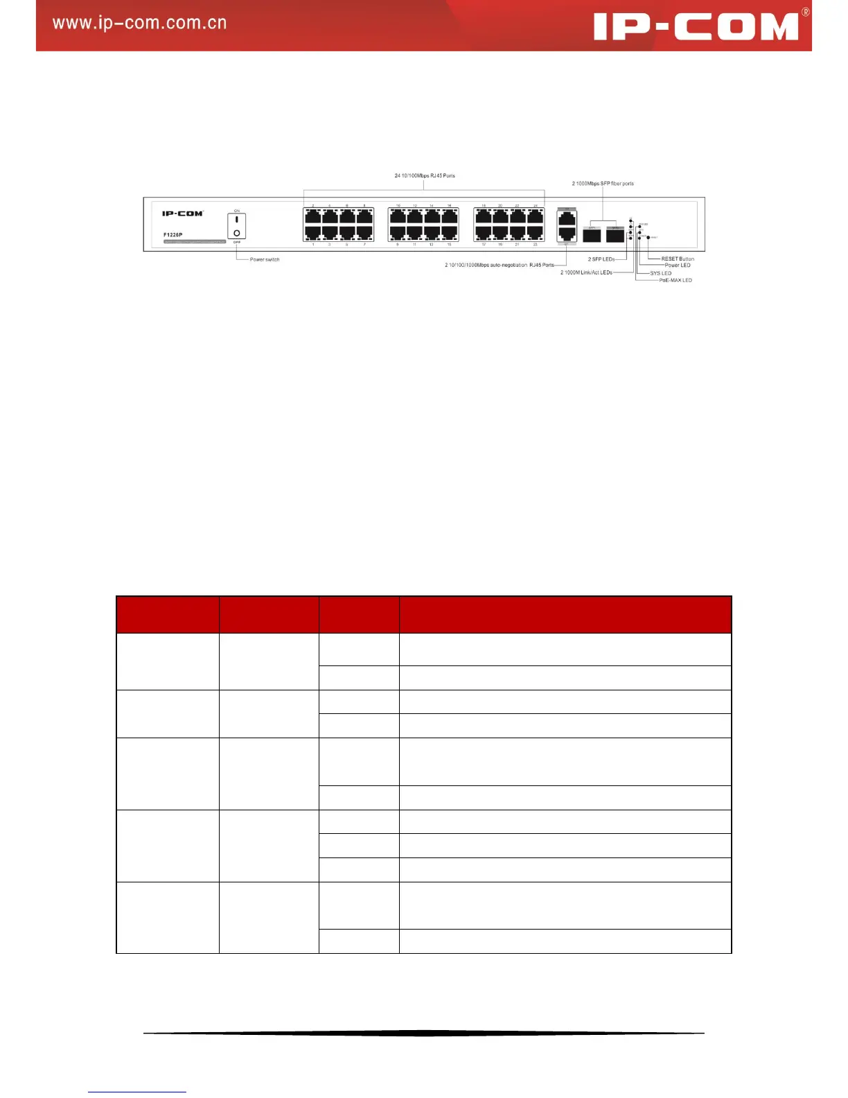
Figure 1 Switch Front Panel
1. RJ45 ports:
24 10/100Mbps and 2 10/100/1000Mbps ports with autosensing and auto-negotiation capabilities
2 1000Mbps SFP fiber ports
2. Status LEDs:
Link/Act1~24: 24 10/100M port status LEDs
PoE1~24: 24 PoE status LEDs
G1~G2: 2 1000M Link/Act port status LEDs (Off when operating at 10/100M speed)
SFP1~SFP2: 2 SFP fiber port LEDs
Power: 1 Power LED
SYS: 1 SYS LED
PoE-MAX: PoE power usage threshold LED
The following table describes the LED designations.
Proper connection to power supply
Improper connection to power supply
System is operating improperly.
System is operating properly.
Reaching max power budget and no more power
available for another new PD
Power available for additional PDs
Link is established on the port.
Packet transmission or reception is occurring on the port.
No link is established on the port.
The PoE powered device (PD) is connected and the port
is supplying power successfully.
No PoE-powered device (PD) connected