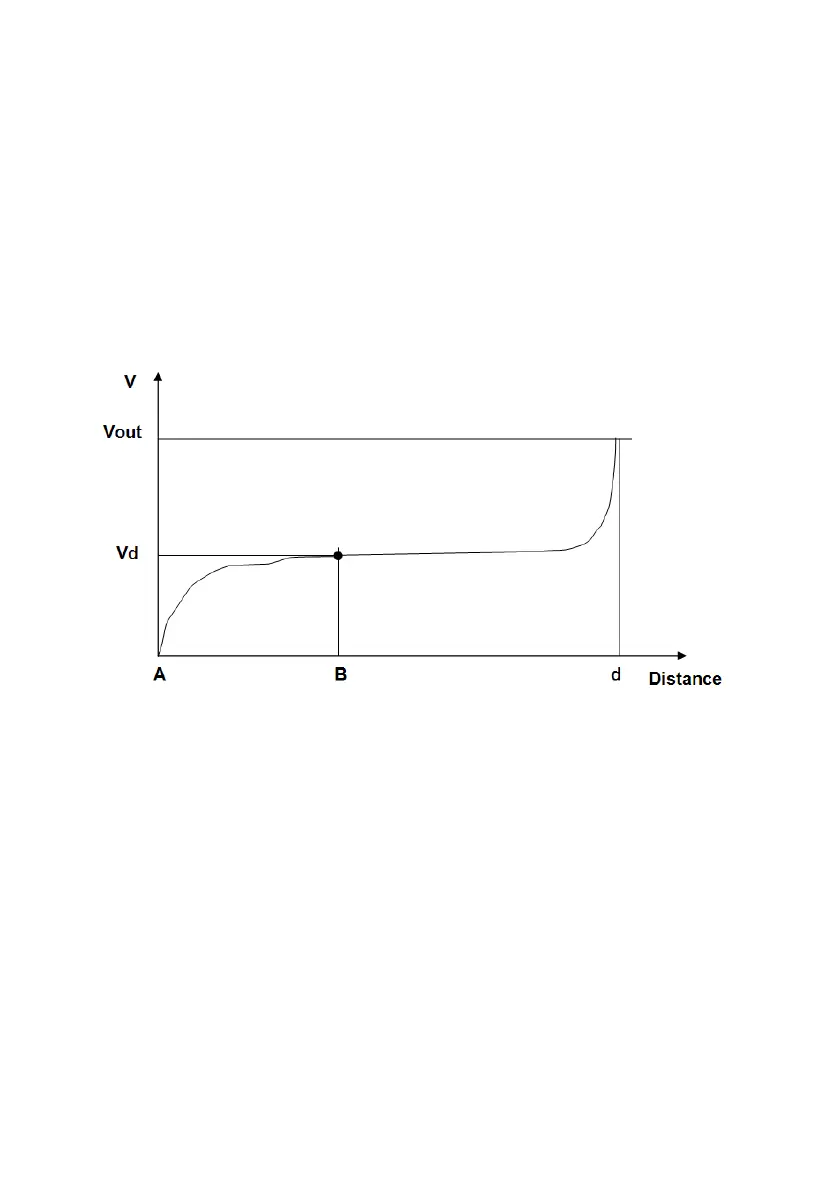
The voltage drop caused by the soil resistance of the system
under test is measured between the connection to the system
grounding (point A) and a voltage spike (point B), that shall be
placed on the line between this point and the auxiliary earth. The
second problem is that the current drops on the system area
resistance as well as on the auxiliary earth resistance. For this
reason, the voltage drop Vd, measured between A and B, as it
moves towards the auxiliary earth goes from zero to the applied
voltage Vout; the voltage to distance curve has the following
shape.
The test is performed moving the voltage probe along the line,
until the voltage drop Vd does not change significantly; as a rule
of thumb, the good point is located from 30% to 50% of the
distance d.
The third problem is that for small systems D is small, and the
cable provided (100 m long) is far enough to reach the auxiliary
earth connection.
With larger systems, such as substations, the dimension becomes
much larger, in the order of hundreds of meters; also the short-
circuit current is much larger than 500 A, and the test current
should be proportionally larger. In this situation it is possible to use
a power cable or an overhead line, out of service, to reach
another substation, whose grounding net can be used as the
auxiliary earth connection. Another mean can be the grounding