45
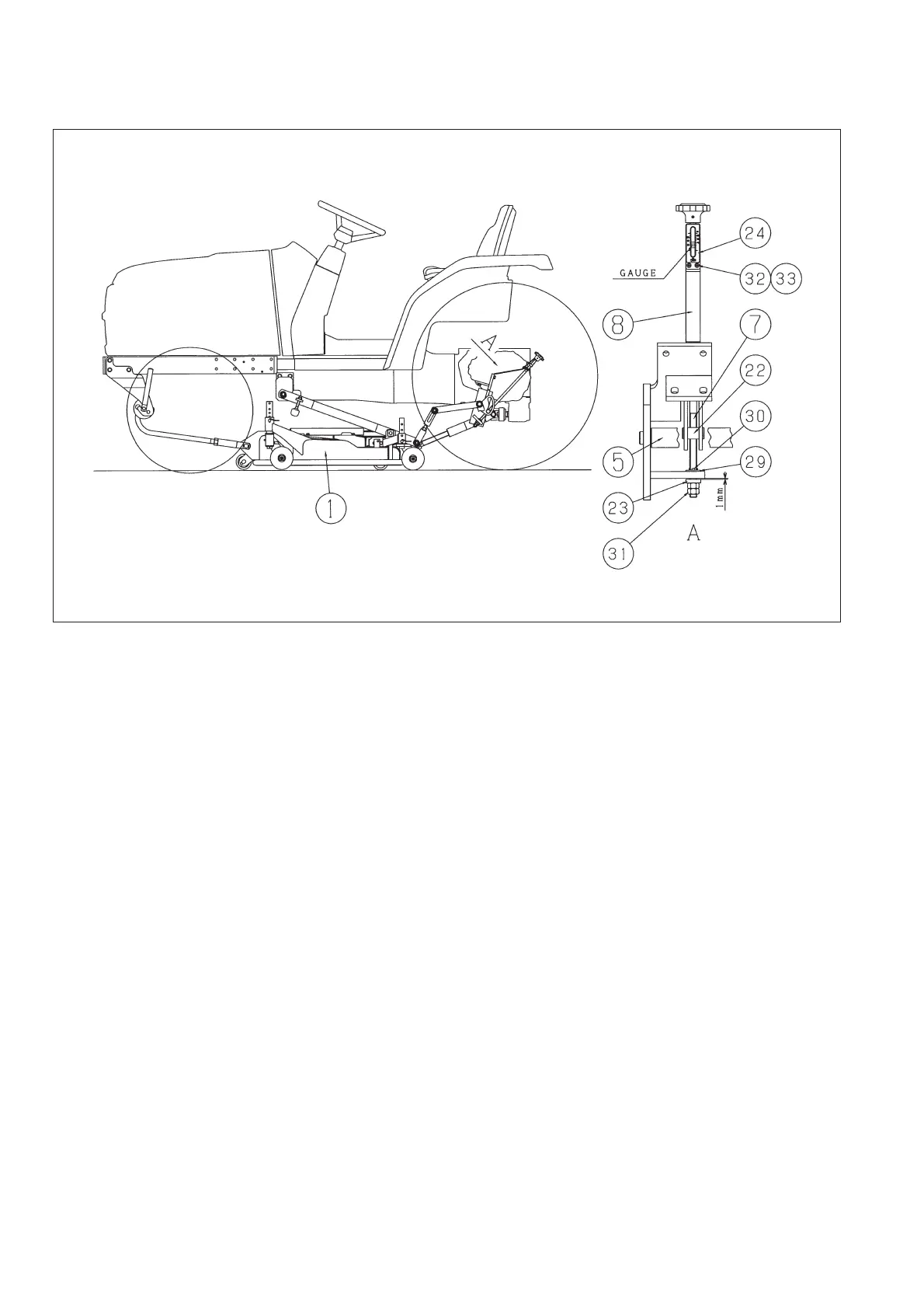
6-6. Installation of the height adjuster
Fig.6-6
a. Lift down the mower deck to the lowest position.
b. Set NUT/ADJUSTER (22) to the long hole of
LINK/REAR (5).
c. Pass SHAFT/ADJUST (7) through the hole of
BRACKET/REAR/RH (8). It is put in the screw
hole of NUT/ADJUST (22) with turning
SHAFT/ADJUST (7) clockwise.
d. Put PLATE WASHER/M12 and SPLIT
PIN/3X35 if the tip of SHAFT/ADJUST (7)
comes out from NUT/ADJUST (22). At this
time, break SPLIT PIN/3X35 (30) completely to
wind it around SHAFT/ADJUST (7).
e. It is turned clockwise until a shaft is turned more
to the right and passed through one more head
hole of the sticks and a nut rises from the link.
Pass SHAFT/ADJUST (7) through the other
long hole of BRACKET/REAR/RH (8) and turn
it clockwise until NUT/ADJUST (7) rises from
LINK/REAR (5).
f. Put WASHER/13X26X06 (23) at the tip of
SHAFT/ADJUST (7) and fix it with 2 pcs of
NUT/M12 (31). At that time, the clearance
between WASHER/13X26X06 (23) and
LINK/REAR (5) is 1mm.
g. Turn SHAFT/ADJUST (7) counterclockwise
until it stops turning.
h. Install PLATE/GAUGE (24) to BRACK-
ET/REAR/RH (8) by using each 2 pcs of
SCREW/M4X12 (32) and NUT/M4 (33). At
that time, install PLATE / GAUGE (24)
with turning the gauge so that the gauge of
SHAFT/ADJUST (7) indicates 30mm
CHAPTER 6. INSTALLATION ON THE TH TRACTOR