User's manual
PFC max 6, PFC max 12 Page 14
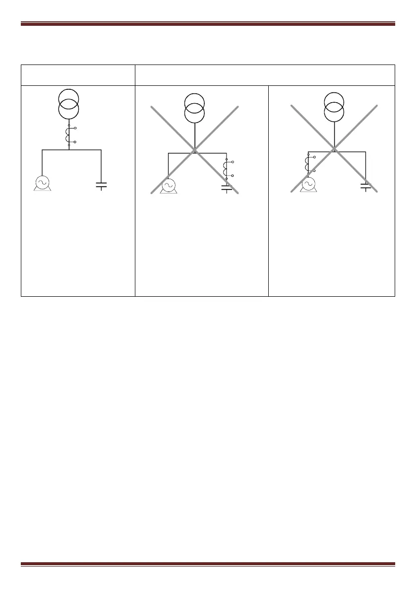
The CT measures the whole
current of loads + capacitor
bank.
In case of malfunction check
that the CT is not
shortcircuited
If CT is placed in this position,
NONE of the CAPACITOR
STAGES WILL CONNECT.
The equipment does not regulate
properly.
If CT is placed in this position
ALL THE CAPACITOR STAGES
WILL CONNECT.
WARNING! This situation may
cause overcompensation,
resonance and overcurrent
Fig. 4.1.- Placement of current transformer (CT)
4.2.3 Cabling cross sections and protections
The supply circuit must be protected by means of fuses or a circuit breaker sized between 0,5 and 2A.
Recommended fuses are gl type (IEC 269) or M type (IEC 127). A main circuit breaker must be provided
in order to allow the disconnection of control circuits from supply (PFC, relays, contactor coils, etc.)
The main switch must be easily accessible. The cabling cross section must be minimum 1,5 mm
2
for the
voltage supply and for the relay outputs and 2,5 mm
2
for the cables connecting secondary of CT to
PFC max . For distances between CT and PFC higher than 10m the cross section of the last must be
increased at a rate of 1 extra mm
2
every 10 m.
TC
S1
S2
P1
P2
LOAD CAPACITORS
TC
S1
S2
P1
P2
LOAD CAPACITORS
LOAD CAPACITORS
TC
S1
S2
P1
P2