User's manual
PFC max 6, PFC max 12 Page 7
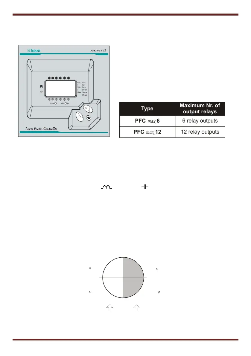
2. GENERAL CHARACTERISTICS
The power factor regulators, of types PFC max6 and
max 12 measure the cosφ (sometimes called
Displacement Power Factor, DPF) in a supply
network and control the connection and disconnection
of power capacitors in order to regulate such
parameter.
The difference between the two types is the number
of output relays, which determines the number of
stages that they can control.
Among the most important features of this PF regulator series we can stand out the following:
- FCP regulation system, which minimizes the number of switching operations.
- Wide choice of switching programs: 1:1:1, 1:2:2, 1:2:4 , 1:1:2:2, etc. which allows the split up of
the total power into up to 31 steps in max 6 or up to 79 steps in max 12
- Four quadrants control (see fig.2.1) , display of the connected stages, of cosφ and active and
reactive power signs (inductive or capacitive )
- LCD display screen with three seven segments characters plus 20 icons to sign up the different
possible working conditions.
- Regulator set-up with only three keys and without disconnecting the device from the supply.
- Multiple supply frequency range, either 50 or 60Hz
- Main electrical parameters displayed during RUN mode
- Easy panel mounting, without the need of tools.
- Front frame size (144 x 144 mm) according to DIN 43 700 (panel hole 138
+1
x 138
+1
mm)
- Measurement and power supply in one single input.
- Four quadrant regulation (suitable for installations importing or exporting energy)
0º
90º
180º
-90º
Imported Power
Exported Power
KW +
kVAr +
Leading/Capacitive
KW -
kVAr -
KW +
kVAr -
Lagging / Inductive
KW -
kVAr +
Cos -
Lagging / Inductive
Cos -
Cos +
Cos +
Leading/Capacitive
Fig. 2.1.- Power signs in four quadrants measurements