User's manual
PFC max 6, PFC max 12 Page 18
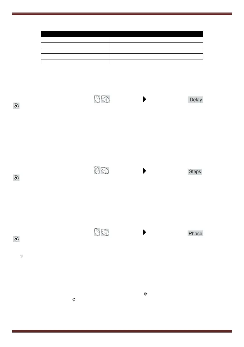
Table 5-2.- Available configuration programs for PFC max devices
5.5 Connection and re-connection time settings:
To set-up this parameter, use the keys until the cursor points to the option , then push
.
This parameter sets up the delay times of the device. The setting value, Tc, is the delay time between the
connection or disconnection of successive capacitor stages. The parameter also sets up the called re-
connection delay, Tr, which is the minimum time that must elapse between the disconnection of a C stage
and its following connection. The range of Tc settings goes from 4s to999s. Tr is automatically set to 5
times Tc (Notice that Tr is needed to guarantee the capacitors discharge). The default setting of Tc is
10s.
5.6 Selection of the number of stages
To set-up this parameter, use the keys until the cursor points to the option , then push
.
This setting allows the selection of the number of stages of the PF compensation equipment. Depending
on the device type, PFC max 6 ó max 12 we can select up to 6 or 12 stages. If the number of stages is less
than 6 or 12 respectively in PFC max6 or max12 the relay number 6 or 12 is automatically assigned as
alarm relay (see paragraph 3.3)
5.7 V,I phase angle setting
To set-up this parameter, use the keys until the cursor points to the option , then push
.
During the set-up of this parameter, the screen shows alternatively one of the options T1 to T6 and the
cos .
This parameter permits the adaptation of the regulator to different options of connection of voltage and
current measurement in the three phase system. The default assumed connection is the one shown in
figs. 4.2 and 4.3, i.e., the current transformer placed in phase L1 and voltage measurement between
phases L2 (terminal C) and L3 (terminal D). Sometimes it’s difficult to guarantee this connection or even
check how it is. To adapt to this unknown situations the PFC max devices allow the selection of different
options, T1 to T6, as shown in table 5.3. To select the right option during start up, you should verify that
there is load and that the loads are mainly inductive with a cos between 0,7 y 1. In this situation try the
different options until the cos screen shows a value between 0,7 and 1.