User's manual
PFC max 6, PFC max 12 Page 5
The adjustment or replacement of components or parts of the unit must be made with original
replacement parts and in accordance with the procedures described in the corresponding
instruction manual.
1.1 Delivery spot check
After unpacking the equipment check the following points:
Check that equipment has not suffered any damage during transport.
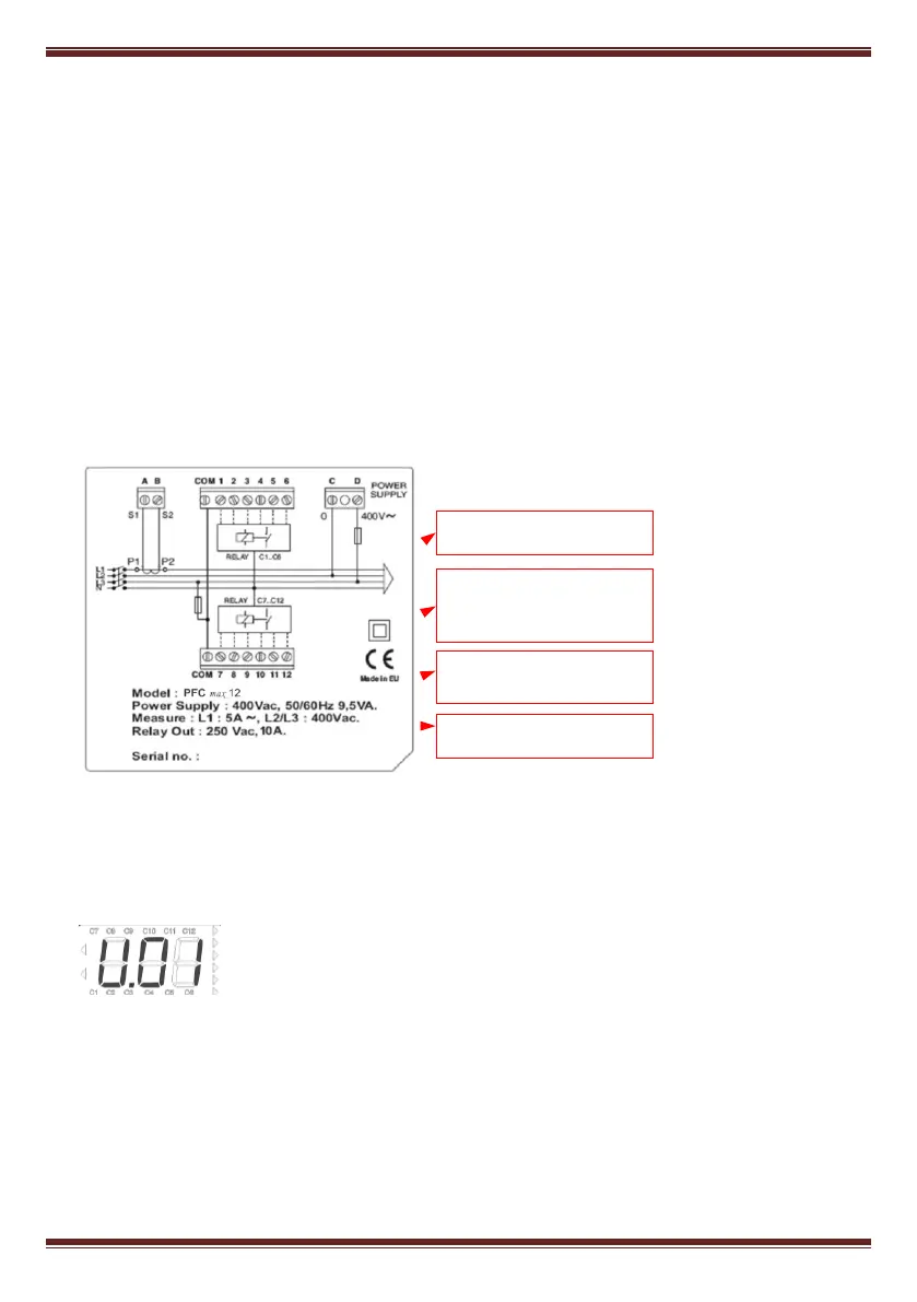
The equipment corresponds to type you ordered. (See label at the rear face, fig. 1.1)
Check that the characteristics in the label are suitable for the site where the regulator has to be
installed. (Supply voltage and frequency, measuring range, etc.)
Follow the instructions in section 3 for installation and set-up.
If you may observe any anomaly during the installation or set-up, contact with Iskra, technical
service.
Fig. 0.1.- Rear face label
1.2 Starting screen
When the PFC max is started (just after supply connection) the screen
shows a code indicating the device version. It’s important to indicate
this code in case of reporting any device fault or error.
1.3 Definitions
In this section we shall give several definitions which will be useful to understand several sections of
this manual.
Terminals available only for
Number of outputs indication
Supply and measuring voltage
Frequency: either 50 or 60 Hz
Output relays characteristics