User's manual
PFC max 6, PFC max 12 Page 16
5. CONFIGURABLE PARAMETERS
In order to adapt the regulator to the loads, certain parameters of the PFC max must be set-up. The
programmable parameters, the required settings and the set-up procedure are explained here below. See
also paragraph 3.5.2 to see how to select the different menu options.
The configurable parameters are listed and shortly explained below.
5.1 Target cosφ
To set-up this parameter, use the keys until the cursor points to the option , then push
The parameter allows the setting of the desired PF in the installation. The regulator will control the
connection of the necessary number of capacitors to get the maximum approach to the target value.
Since the regulation is in a stepwise mode, the regulator will add a new step when the demanded power
is at least 70% of the lower available step power and will remove a step when the excess is also a 70% of
the lower available step power. The cosφ adjustment range is from 0,85 inductive to 0,95 capacitive.
5.2 Smaller available capacitor step
To set-up this parameter, use the keys until the cursor points to the option , then push
This parameter, named C/K, indicates the reactive current supplied by the smaller capacitor step,
measured at the secondary side of the current transformer (CT). Therefore, the setting value depends on
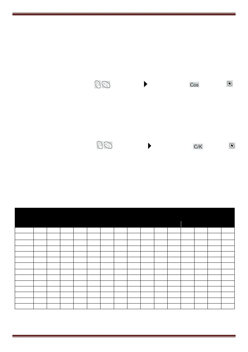
the power of the smaller capacitor step, on the CT ratio and on the supply voltage. Table 5.1 gives the
setting values of C/K for a 400 V phase to phase supply for different CT ratios and different values of
smaller capacitor step (kvar). For conditions other than those given in table 5.1, the paragraph 5.1.3
shows a simple calculation to obtain the C/K value. See also foot NOTE.
Table 5-1.- C/K factor according to smaller capacitor power and CT ratio.
Smaller capacitor power in kvar, at 400V (*)
(*) NOTE: For supply voltages other than 400V the C/K factor obtained from the table must be multiplied by the ratio (400 / V
supply
)