User's manual
PFC max 6, PFC max 12 Page 19
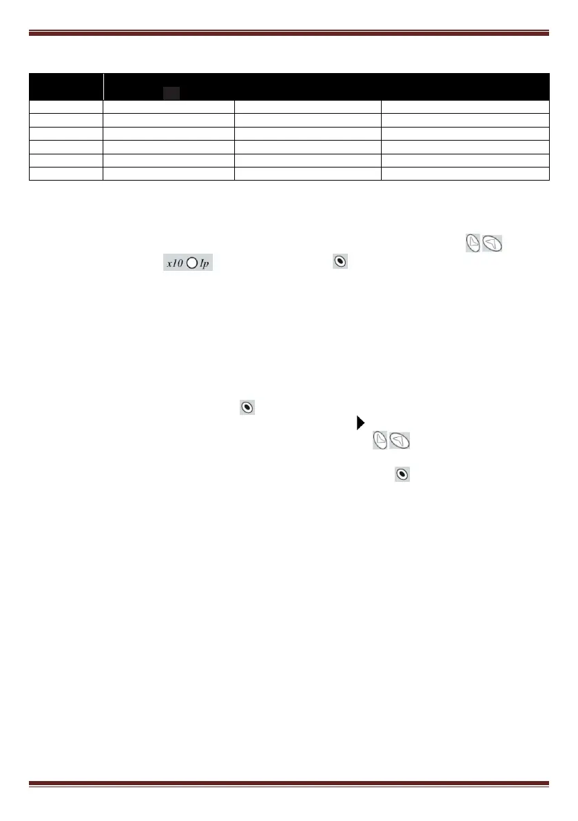
Table 5-3.- Phase shift options in PFC max
V-I phase shift at
cos =1
L3 (P1-P2 or S1-S2 reversed)
L1 (P1-P2 or S1-S2 reversed)
L2 (P1-P2 or S1-S2 reversed)
5.8 Programming the CT rated current (primary)
The set-up of this parameter can be selected at the bottom of the menu options. Use the keys
until the bottom red LED is flashing and push . The display will show the assumed CT
primary current. Set the value according to the CT used to measure installation current. The adjustment
range is from 0 to 999 and with the x10 option allows a rated primary current up to 9990 A. By default the
secondary of CT is assumed to be 5 A.
6. SET-UP MENU AND PROCEDURE
6.1 How to access the set-up menu
To access the set-up menu, press the key for more than 1s (This is designated as long push in table
6.1 , which gives a summary of the set-up procedure). The pointer starts blinking and points to the
parameter to be adjusted. Select the parameter by means of the keys .
After the long push and in case that all the capacitor stages are disconnected, the device jumps to the
set-up status. In case that there are some stages connected, keep the key pushed while the regulator
disconnects the connected stages sequentially and respecting the programmed delay time. Once all the
stages have been disconnected the device enters the set-up status and allows the adjustment of the
different parameters. A schematic diagram of the set-up menu showing the different navigation paths is
shown in table 6.1. The meanings of the different adjustable parameters have been explained in
paragraph 5.1.
F