18-24
18. BF200D • BF225D • BF250D iST
®
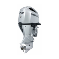
6. Make a mark on the panel indicator cable at
5-1/2 inches from the back of the connector.
This is where the tie wrap will be located.
Make a mark on the panel indicator cable at
13 inches from the back of the connector. This
is where the front of the grommet will be
located.
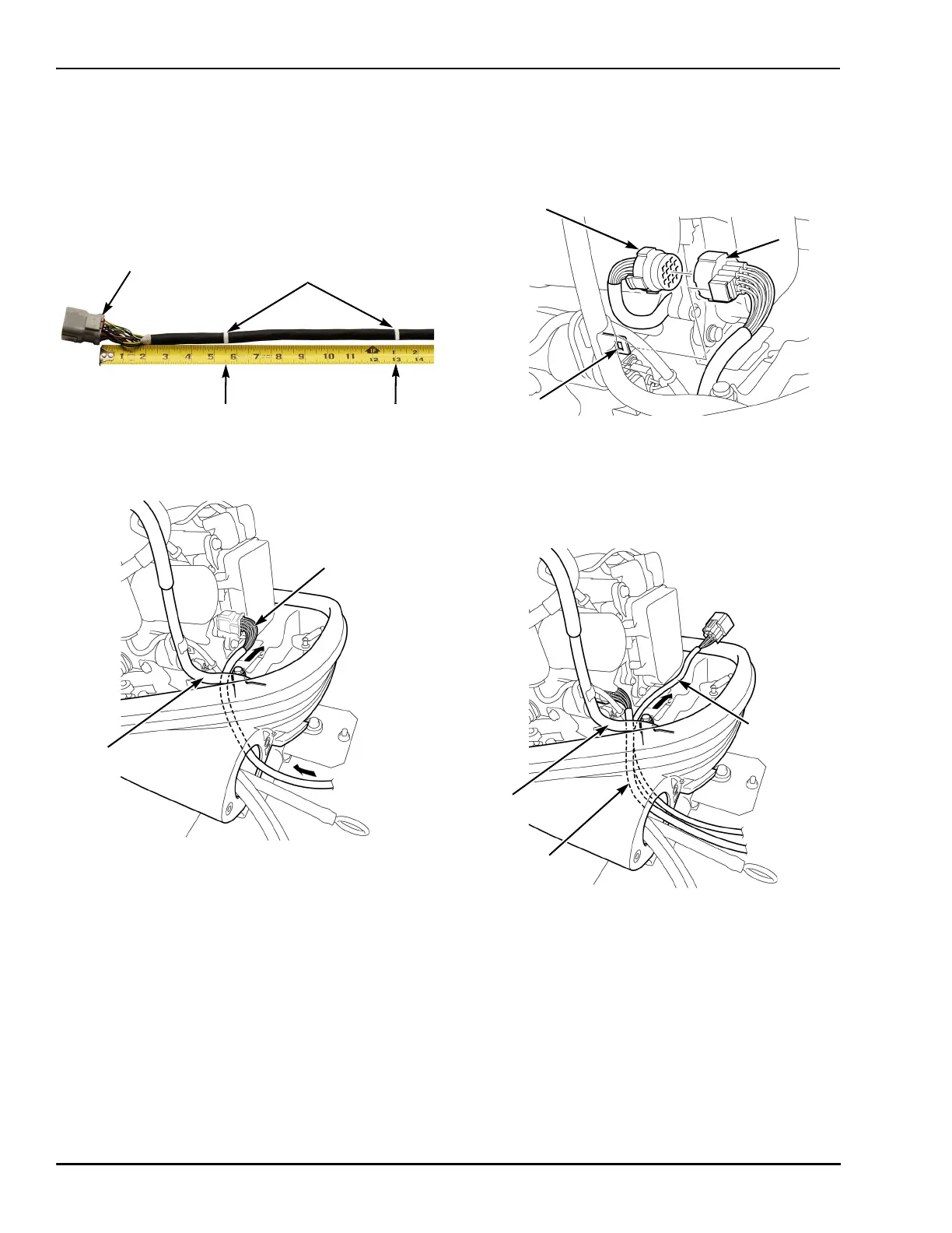
7. Route the panel indicator cable through the
separate cover, and then through the engine
under case, passing behind the fuel tube.
8. Connect the panel indicator cable connector
to the main harness connector.
Install the connector onto the connector
bracket.
9. Route the NMEA interface cable through the
separate cover, and then through the engine
under case, passing behind the fuel tube and
panel indicator cable.
PANEL INDICATOR
CABLE CONNECTOR
13 in
MARK (2)
5-1/2 in
PANEL
INDICATOR
CABLE
FUEL
TUBE
CONNECTOR
BRACKET
MAIN
HARNESS
CONNECTOR
PANEL
INDICATOR
CABLE
CONNECTOR
NMEA
INTERFACE
CABLE
FUEL
TUBE
PANEL
INDICATOR
CABLE