18-25
18. BF200D • BF225D • BF
250D iST
®
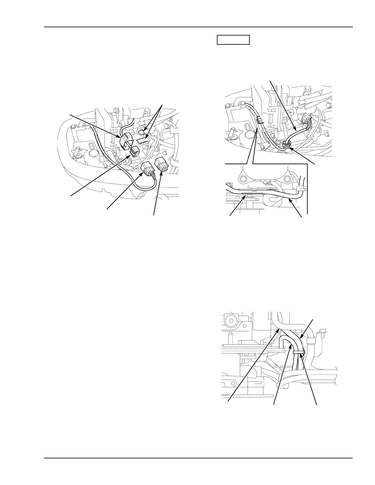
10. Remove the connector suspension from the
stays and remove the dummy connector from
the main harness connector.
Connect the NMEA interface cable connector
to the main harness connector, and then
reinstall the connector suspension onto the
connectors. Install the connector suspension
onto the stays.
11. Route the NMEA interface cable through the
harness clip, and then route it through the
bottom edge of the electric parts case.
Ensure the NMEA interface cable is routed
behind the panel indicator cable to prevent
chafing.
12. Wrap, but do not tighten, the NMEA interface
cable and panel indicator ca
ble with the
harn
ess band clip, and then install the clip on
the fuel tube stay.
Position the panel indicator cable 5-1/2"
white
ma
rk so it aligns with the harness band.
Tighten the harness band clip, and
then cut
the excess.
13.
Ensure the panel indicator cable and
the
NMEA in
terface cable are routed unde
r the
sh
ift link guide.
DUMMY
CONNECTOR
CONNECTOR
SUSPENSION
MAIN
CONNECTOR
HARNESS
NMEA
INTERFACE
CABLE
CONNECTOR
STAY (2)
HARNESS
CLIP
NMEA INTERFACE
CABLE
ELECTRIC
PARTS CASE
NMEA INTERFACE
CABLE
PANEL INDICATOR
CABLE
NMEA
INTERFACE
CABLE
HARNESS BAND
CLIP
FUEL
TUBE