ENGINE MECHANICAL 6A–57
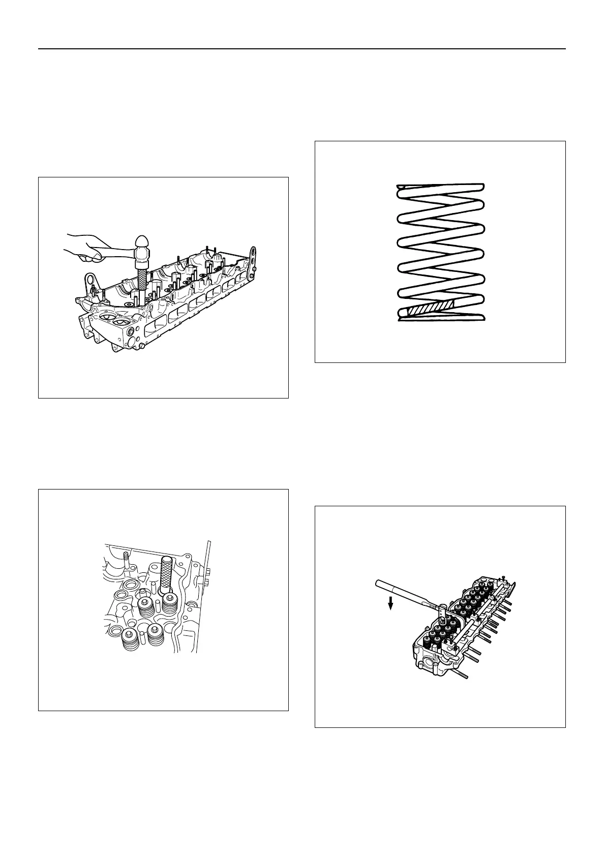
2. Attach the valve guide replacer 5-8840-2628-0 to
the valve guide.
3. Use a hammer to drive the valve guide into
position from the cylinder head upper face.
4. Measure the height of the valve guide upper end
from the upper face of the cylinder head.
Valve Guide Upper End Height (Reference):
19 mm (0.748 in)
7. Install the spring seats.
8. Install the valve stem seals on the valve guide.
1. Apply engine oil to the oil seal inner face.
2. Use the oil seal installer 5-8840-2625-0 to install
the oil seal to the valve guide.
9. Install the valves.
Apply engine oil to the intake valves and exhaust
valves.
10.Install the valve springs.
1. Place the cylinder head on a flat wooden surface.
2. Install the valve springs with their fine pitched end
(painted) facing down.
Colored
Intake Valve: Light blue
Exhaust Valve: Yellow
11.Install the valve spring upper seats.
12.Install the split collars.
1. Use the spring compressor 5-8840-2621-0 to
compress the valve spring.
2. Install the split collars to the valve stem.
Do not allow the valve to fall from the cylinder
head.
3.Set the split collars by tapping around the head of
each collar with a rubber hammer.
011MX024
011MX020
014EY00067
011MX017

 Loading...


