ENGINE MECHANICAL 6A–89
Connecting Rod Alignment
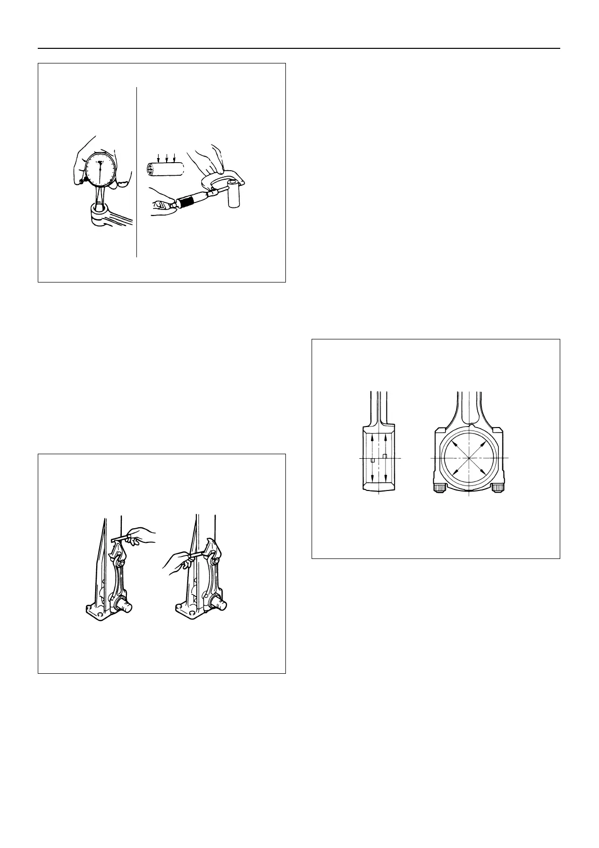
Use a connecting rod aligner to measure the distortion
and the parallelism between the connecting rod big end
hole and the connecting rod small end hole.
If either the measured distortion or parallelism exceeds
the specified limit, the connecting rod must be replaced.
Connecting rod alignment
Per length of 100 mm (3.94 in.)
Standard: 0.05 mm (0.002 in.) or less
Limit: 0.20 mm (0.008 in.)
Crankshaft and Connecting Rod Bearing
Clearance
1. Clean the crankshaft, connecting rod, bearing cap,
and bearings.
2. Install the bearing to the connecting rod and bearing
cap.
3. Apply a coat of molybdenum disulfide grease to the
bearing cap bolt threads and setting faces.
4. Prevent the connecting rod from moving.
5. Tighten the bearing cap to the specified torque.
Connecting rod bearing cap bolt torque
1st step: 39 N·m (4.0 kgm/29 lbft)
2nd step: 60 deg.
3rd step: 30 – 60 deg.
6. Use a dial indicator to measure the connecting rod
bearing inside diameter.
Crankpin and connecting rod bearing clearance
Standard: 0.037 – 0.076 mm (0.0015 – 0.0030 in.)
Limit: 0.1 mm (0.0034 in.)
7. If the clearance between the measured bearing
inside diameter and the crankpin exceeds the
specified limit, the bearing and/or crankshaft must be
replaced.
015EY00102

 Loading...


