6A–90 ENGINE MECHANICAL
Connecting Rod and Crankshaft Clearance
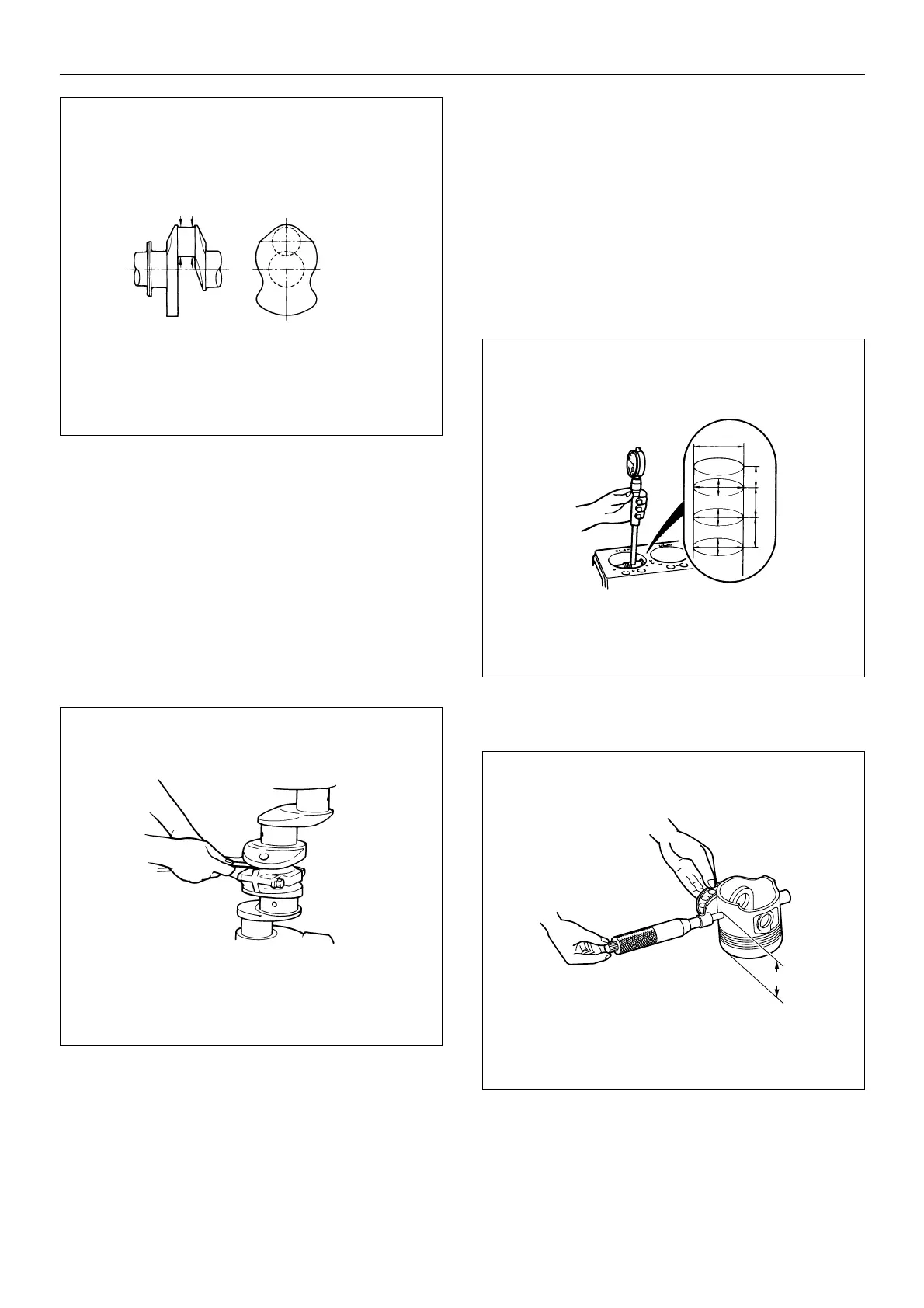
1. Fix the connecting rod assembly to the crankshaft
using the specified torque.
2. Use a feeler gauge to measure the clearance
between the connecting rod and crankshaft.
If the measured value exceeds the specified limit, the
connecting rod must be replaced.
Connecting rod and crankshaft clearance
Standard: 0.17 – 0.30 mm (0.0067 – 0.0118 in.)
Limit: 0.35 mm (0.0138 in.)
Piston and Liner Bore Clearance
If the cylinder liner has been replaced, install the piston
using service parts. The cylinder liner bore and pistons
have only one grade. It is not necessary to select the
piston grade.
1. Measure the cylinder liner bore. (Reference)
Refer to the “Cylinder Liner Bore Measurement.”
Measuring Point 130 mm (5.118 in.)
Cylinder liner bore
Standard: 115.031 – 115.050 mm
(4.5288 – 4.5295 in.)
2. Measure the piston outside diameter (Reference).
Piston Measuring Point: 80 mm (3.15 in.)

 Loading...


