SERVICE INFORMATION 0B–7
Valve Clearance: 0.4 mm (0.0016 in)
2. Insert a feeler gauge between the rocker arm and
the bridge and adjust the valve clearance by
turning the adjusting screw on the rocker arm until
there is a sight drag on the feeler gauge. Tighten
the lock nut securely.
3. With a feeler gauge inserted, screw in the
adjusting screw on the bridge gradually until it
touches the end of the valve stem. Make sure that
the movement of the feeler gauge becomes stiff.
4. In this condition, the opposite end of the bridge is
raised. Readjust by loosening the adjusting screw
on the bridge until there is a slight drag on the
feeler gauge. Tighten the lock nut securely.
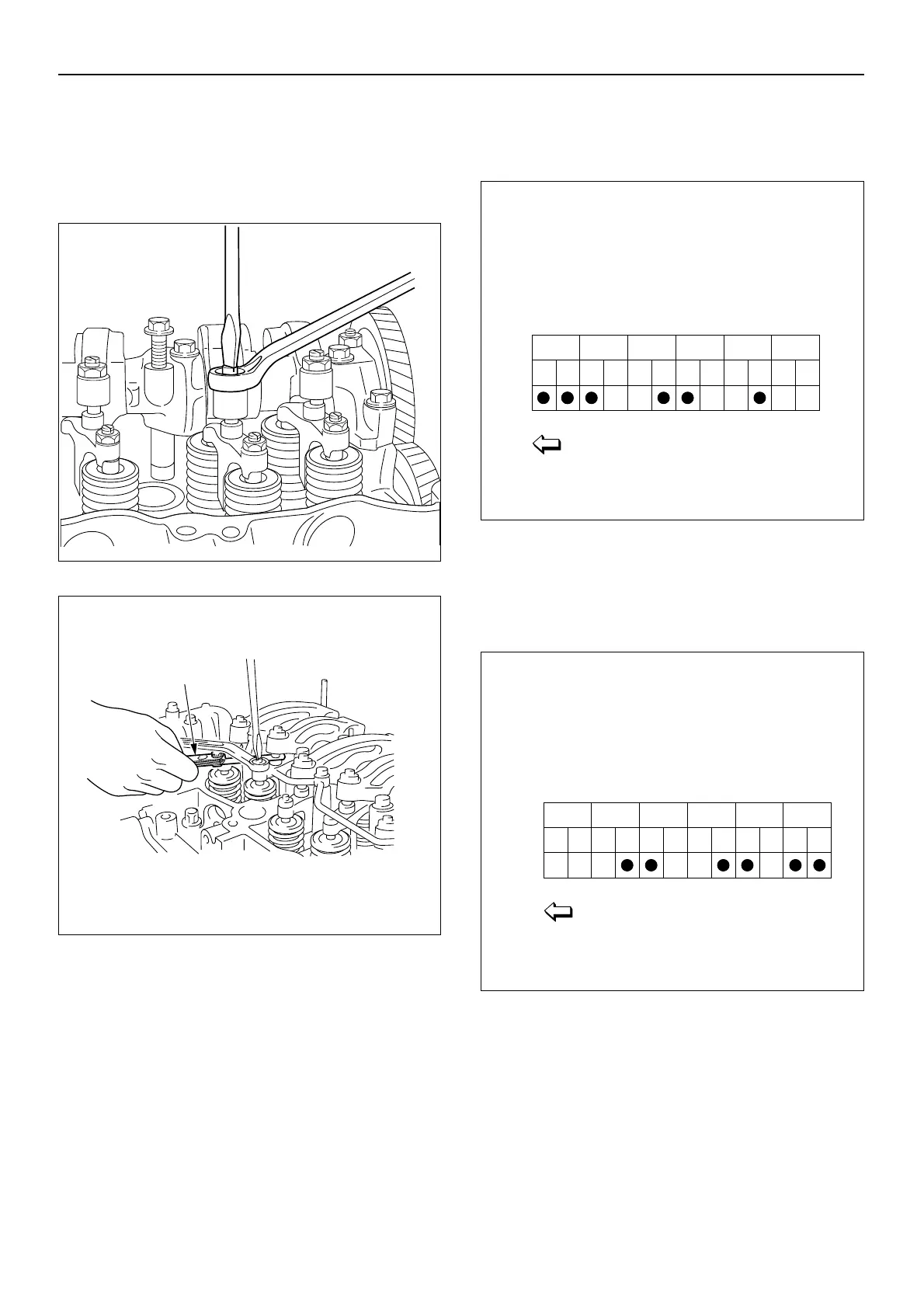
4. Rotate the crankshaft 360 degrees and realign the
T.C. mark on the flywheel with the pointer. Adjust
clearance for remaining valves.
The “●” mark in the illustration indicates the cylinders
and valves to be adjusted.
NOTE: Be sure to move the No. 1 cylinder to TDC on the
compression stroke after completing the valve clearance
adjustment procedure.
Torque: 22 N·m (2.2 kg·m/16 lb·ft)
Rocker Arm Adjusting Screw Nut
Torque: 22 N·m (2.2 kg·m/16 lb·ft)
Bridge Adjusting Screw Nut
014MV001

 Loading...


