0B–8 SERVICE INFORMATION
Intake and Exhaust Valve Arrangement
I : Intake valve. E: Exhaust valve
Cylinder No. 1 2 3 4 5 6
Valve Names I EIEIEIEIEIE
No. 1 cyl. at TDC on compression ●● ●● ●● ●● ●● ●●
No. 6 cyl. at TDC on compression ●● ●● ●● ●● ●● ●●
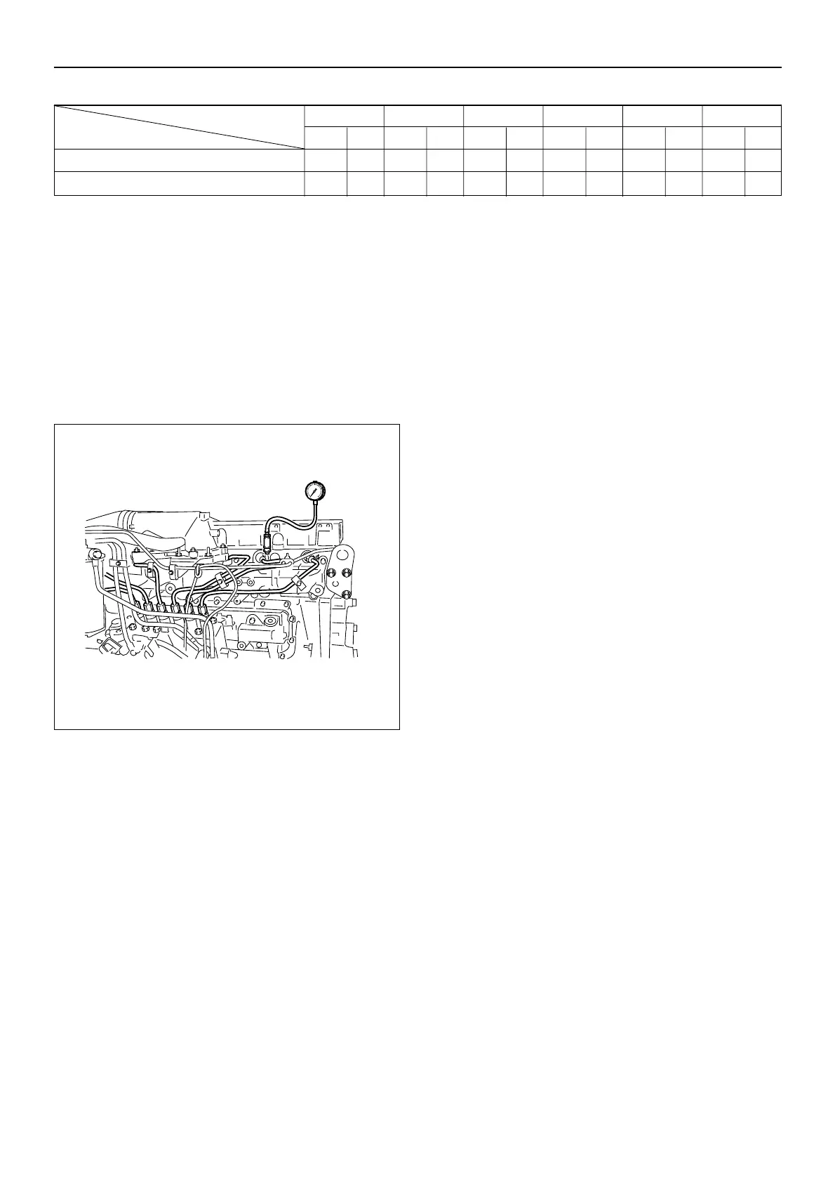
Compression Pressure Measure
To measure the compression pressure, the engine must
be cold. Engine coolant temperature should be at 20°C.
Battery and starter motor condition must be normal.
1. Remove the glow plug and the injection fuel pipe from
each cylinder.
2. Install the compression gauge adapter 5-8840-2622-
0 to the glow plug installation hole.
3. Install the compression gauge to the compression
gauge adapter.
4. Crank the engine with starter motor (about 200 min
–1
)
and take the compression gauge reading.
5. Repeat the procedure (Steps 2 to 4) for the remaining
cylinders.
Compression Pressure
Standard : 3.24 MPa (33 kg/cm
2
/ 470 psi)
Limit : 2.26 MPa (23.0 kg/cm
2
/ 327 psi)
Compression pressure should be approximately the
same for each cylinder.
A variation exceeding 200 kPa (2.0 kg/cm
2
/ 28 psi) is
unacceptable.
040EY00003

 Loading...


