6A–40 ENGINE MECHANICAL
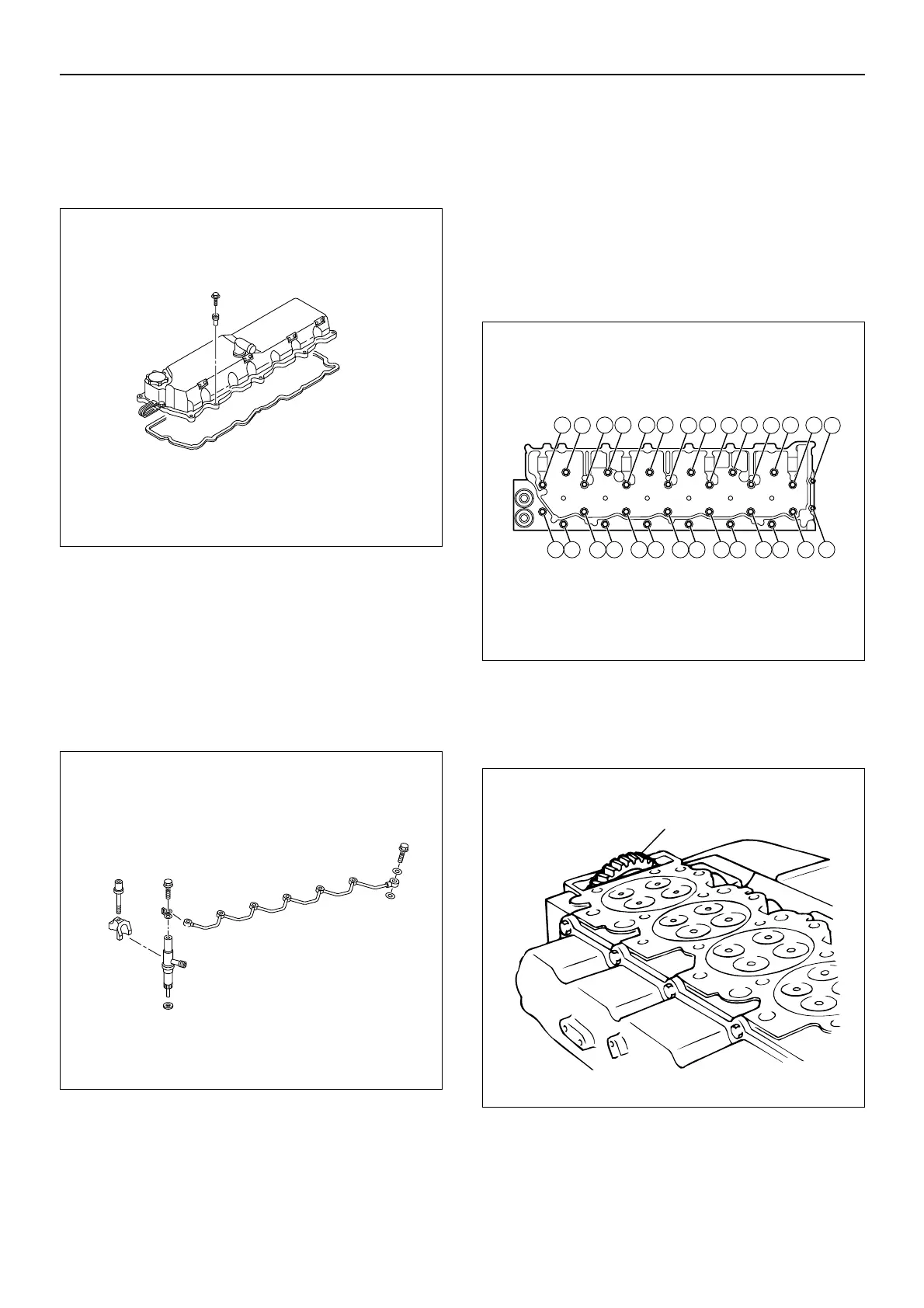
1. Remove the head cover.
2. Remove the cylinder head cover gasket.
Discard the gasket.
NOTE: Be careful not to lose the collars inserted into the
cylinder head cover assembly.
3. Remove the rubber plug.
4. Remove the rocker arm shaft assembly.
Refer to “Rocker Arm Assembly Removal” in this
manual.
5. Remove the camshaft with the gear.
Refer to “Camshaft Removal” in this manual.
6. Remove the leak off pipe.
7. Remove the injection nozzle holder.
8. Remove the glow plug connector.
• Remove the injection nozzles and glow plugs
before removing the cylinder head.
9. Remove the bridge cap.
10.Remove the bridge.
NOTE: Keep the bridges in order for reassembly to their
original positions.
11.Remove the cylinder head.
• Loosen the cylinder head bolts a little at a time in
the numerical order shown in the illustration.
• Clean the cylinder head surfaces and remove the
sealant residue.
CAUTION: Failure to loosen the cylinder head bolts in
numerical order a little at a time will damage the cylinder
head lower surfaces.
CAUTION: The idler gear C (1) projects from the
cylinder head lower side and is easily damaged. Great
care must be taken to avoid damaging the idler gear C
when the cylinder head is removed from the engine.
13.Remove the cylinder head gasket.
Discard the gasket.
010MX004

 Loading...


