OUTPUT
4-16Ω100V
MUTE
AUDIO AUX2 AUX1
OUTPUT INPUT
MIC
LINE
PHANTOM
MIC
LINE
PHANTOM
MIC
LINE
PHANTOM
MIC
LINE
PHANTOM
MIC 4 MIC 3 MIC 2
EMC IN
MUTE
G G G
G
+
MIC 1
FM ANT
G
100V/4-16Ω
NC NC
7
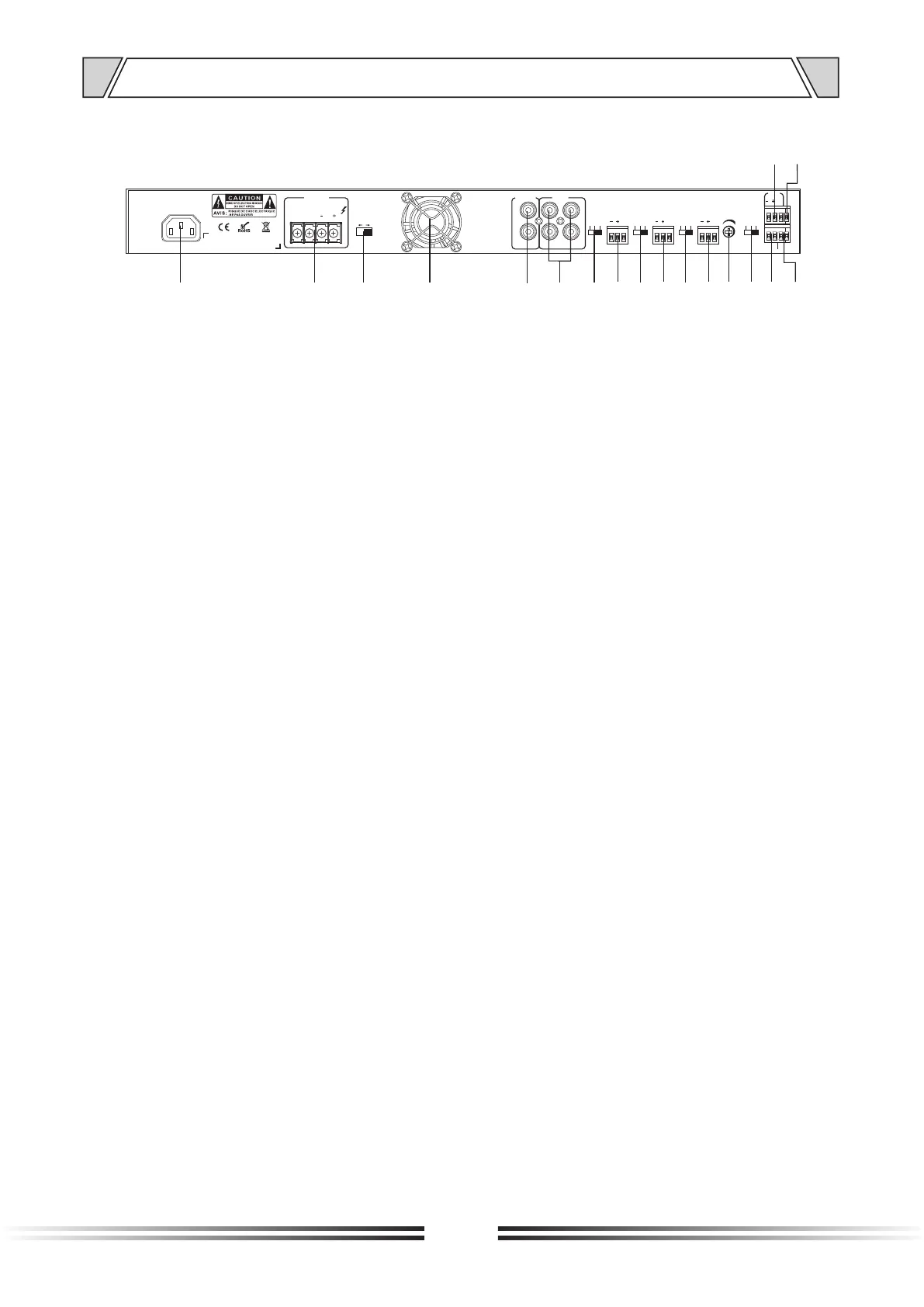
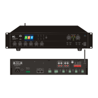
4. NOMENCLATURE AND FUNCTIONS
4.3 REAR PANEL
1
2
3
5 7
4
15
6
8 9
1011
12
13
14
16
17
18
1. AC power input socket
2. 100V/4-16Ω output interface
3. 100V / 4-16Ω speaker output switch
4. Cooling fan
5. Line output interface, used to connect the line input interface
6. 2 channel AUX input interface, used to connect AUX output interface
7. Line input /Mic input /Phantom power switch for MIC4
8. MIC4 Balance input
9. Line input /Mic input /Phantom power switch for MIC3
10. MIC3 Balance input
11. Line input /Mic input /Phantom power switch for MIC2
12. MIC2 Balance input
13. MUTE control switch
14. Line input /Mic input /Phantom power switch for MIC1
15. EMC input interface
16. MUTE signal input port
17. FM radio antenna interface
18. MIC1 Balance input