Basic Operation
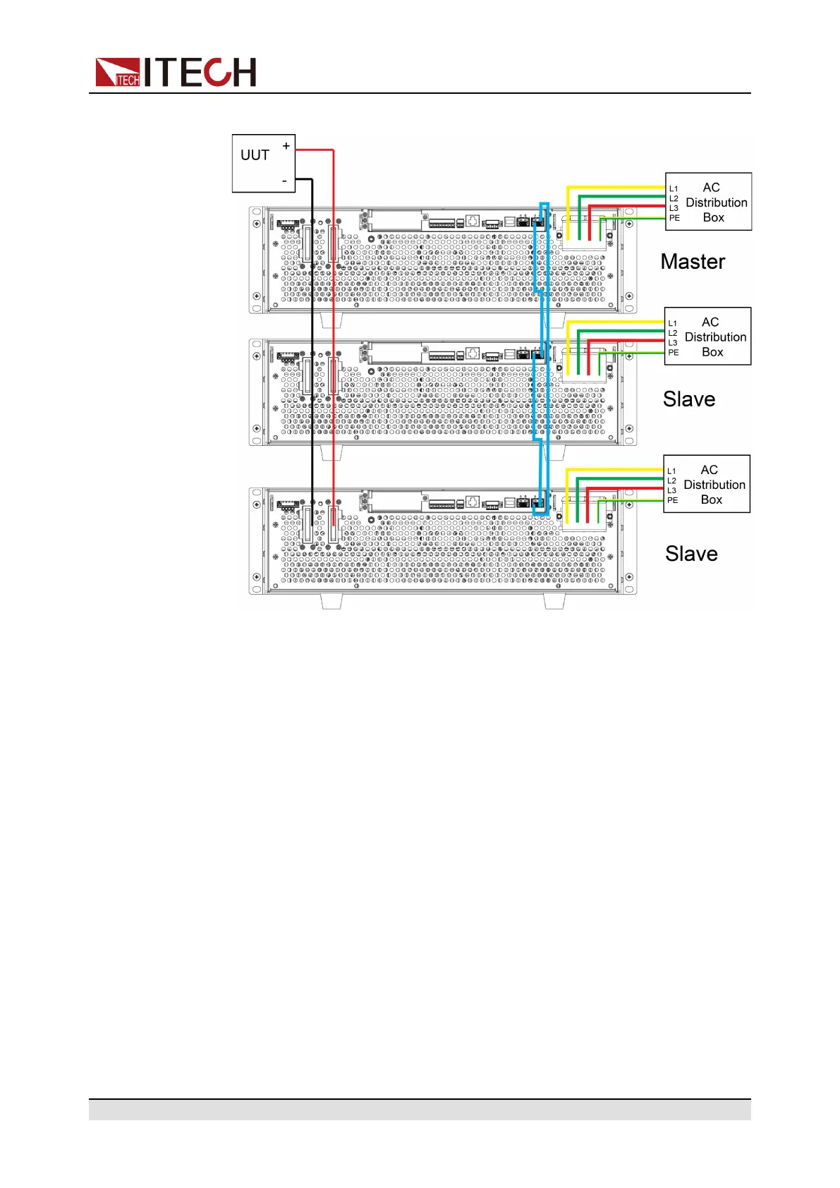
Figure 5–1 Wiring connection diagram
a. Connect the AC input terminals of the three units separately, and connect
them to the AC distribution box.
b. Connect the DC output terminals of the three units in parallel and connect
them to the DUT.
c. Refer to the blue wiring legend in the figure, connect the System Bus (i.
e., the fiber outer ring interfaces TX and RX) for fiber-optic communica-
tion between the master and slaves.
• Three 3U single instruments parallel
Copyright © Itech Electronic Co., Ltd.
163