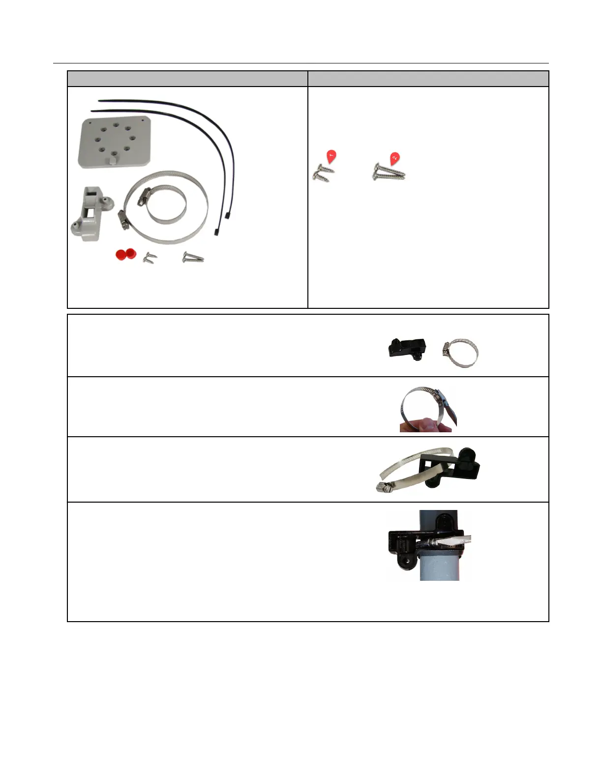
Itron part number Description
• 2 cable ties
• 1 adapter plate
• and the following screws
1. SCR-0215-001 (2) #8-16 x ½ inch slotted
pan-head tapping screw, corrosion-resistant
steel. Attaches the adapter plate to the pipe
bracket.
2. SCR-0215-002 (2) #8-16 1-inch slotted pan-
head tapping screw, corrosion-resistant steel.
Attaches the ERT module to the adapter
plate.
1. Remove the pipe bracket and clamp from the
kit.
2. Loosen the band clamp screw until the end of
the band releases.
3. Push the end of the clamp's band through the
holes in the pipe bracket as shown.
4. Place the band clamp around the pipe. The
band will loosely wrap around the pipe.
1. Push the end of the band through the band
clamp screw assembly.
2. Turn the band clamp's screw assembly to fit
into the pipe bracket opening.
3. Tighten the clamp screw until the band clamp
is secure on the pipe.
Mounting the 100G Series Remote Gas ERT Module
100G Series Gas ERT Module Installation Guide, Remote Mount TDC-0824-017 9
Proprietary and Confidential