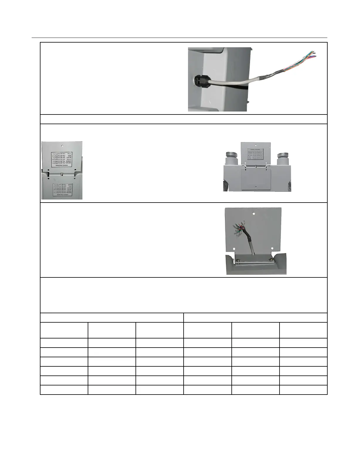
3. Loosen the cable gland and pull the cable out
until it extends 7.5 to 8" out of the cable gland.
4. Tighten the cable gland. Do not use a pliers or wrench to tighten the cable gland.
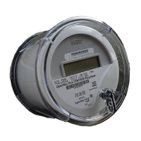
5. Rotate one bracket. Route the meter cable through the holes located at the bend of the mounting
brackets.
6. Attach the brackets to the meter using the
previously removed screws.
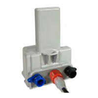
7. Splice the meter pulse output wires to the ERT module wires using gel cap connectors. Follow
the wire connections for the D800/D1000 to 100G ERT module wire connections below.
Note: Use a crimping tool compatible with gel-connectors. Details on using the crimping tool are
included in the mounting installation section of this document.
D800/D1000 meter ERT module
Pulse output Wire Pulse output 1 Pulse output 2 Pulse output 1
with fault
Pulse output 2
with fault
Output 1+ Brown White and blue White
Output 1- Green Red Red
Output 2+ White White and blue White
Output 2- Black Red Red
Output 3+ Red White White
Output 3- Blue Blue Blue
Specific Meter Manufacturer Installation
100G Series Gas ERT Module Installation Guide, Remote Mount TDC-0824-017 37
Proprietary and Confidential