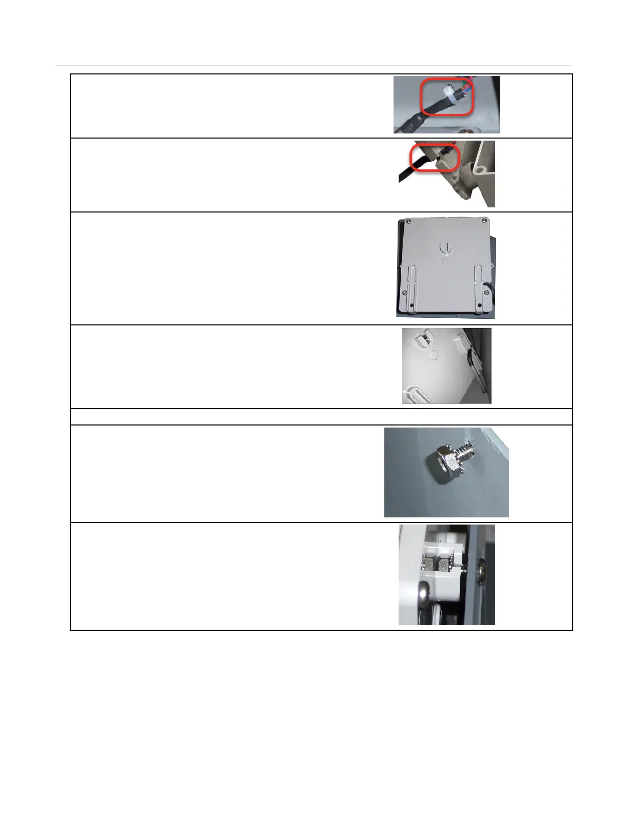
8. Install a cable tie strain relief on the cable
approximately 1/8" from the end of the cable
insulation.
9. Position the cable so the strain relief is just
inside the slot on the module's backplate.
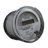
10. Carefully fold the ERT module wires into the
module's housing. Do not pinch the wires of gel
connections between the housing and the
backplate.
11. Install the four back plate screws using the
T-15 Torx screws supplied with the ERT module.
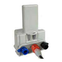
12. Route the cable through the channel in the backplate standoffs.
13. Insert the 8-32 x 1/2" screw into the top hole
in the meter mounting bracket and thread one of
the Kep nuts loosely onto the end of the screw.
14. Tilt the bottom of the ERT module away from
the mounting bracket and slide the notched
mounting hub onto the screw and Kep nut. Do
not tighten the screw.
Specific Meter Manufacturer Installation
100G Series Gas ERT Module Installation Guide, Remote Mount TDC-0824-017 38
Proprietary and Confidential