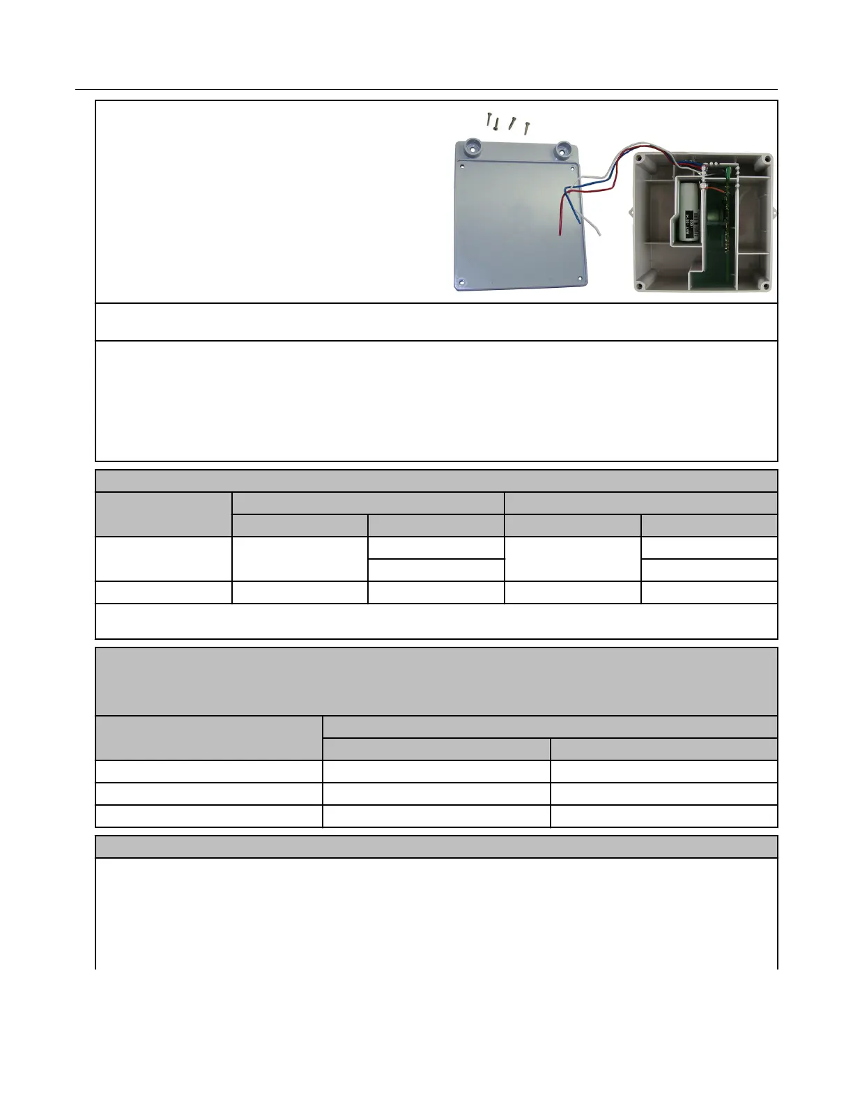
1. Remove the ERT module backplate (4 screws) to
expose the module lead wires. The backplate and
screws will be re-installed on the ERT module later
in this procedure so store them (temporarily) in a
safe, secure place.
2. Insert the lead wires from the module into new 3M gel connectors (Itron part number
CON-0023-001) together with the lead wire from the meter cable (see wiring connections).
3. Crimp the connectors using a 3M hand-held crimping tool.
Important: Use a crimping tool compatible with gel-connectors. Do not use a standard pliers for
crimping gel connectors. For more information, see Using gel-cap connectors to complete wiring
connections on page 72.
Follow the correct wiring configuration for your Romet corrector or meter from the following wiring
parameters.
Standard AdEM Romet 43-035-40 cable wiring
Connection Corrected count Uncorrected count
Romet cable ERT wire Romet cable ERT wire
Pulse Output 1+ Green White Red White
Blue Blue
Pulse Output 1- White Red Black Red
Note: This wiring configuration will not allow a cut cable tamper.
Romet PG9 pigtail cable wiring
Note: The pigtail cable is the cable extruding from the back of the AdEM corrector. You must select
the pigtail cable at the time the AdEM corrector is ordered.
Connection Corrected count
Romet cable ERT module
Pulse Output 1+ White White
Pulse Output 1- Red Red
Cut Cable Alarm Green Blue
Romet ECM2® meter wiring
The Romet ECM2
®
meter has three Form "A" outputs that can be configured at the factory to
provide any combination of the following three outputs:
• Uncorrected volume (UNC VOL)
• Corrected volume (COR VOL)
• Alarm
Specific Meter Manufacturer Installation
100G Series Gas ERT Module Installation Guide, Remote Mount TDC-0824-017 57
Proprietary and Confidential