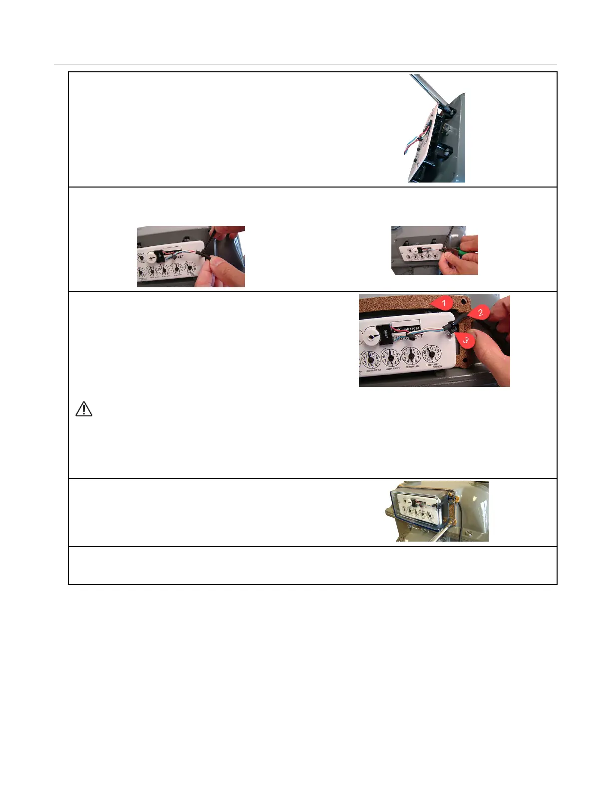
18. Align the index wriggler with the meter's drive
dog. Install the index on the meter using the
index mounting screws. Tighten one index screw
two turns. Install and tighten the remaining index
screw. Tighten the first index mounting screw
completely (alternating fashion).
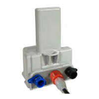
19. Install a strain-relief cable tie about 1-1/4-inch from the encoder cable's stripped end. The cable
tie must be inside the index cover after the cover is installed on the meter. Remove any excess
cable tie with a side-cutting pliers and dispose the excess cable tie.
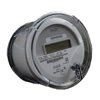
20. Remove the protective backing on the
replacement gasket to expose the adhesive side
of the gasket. Align the gasket (1), encoder cable
(2), and cable tie (for strain-relief) (3) on the
meter as shown.
Caution: Route the encoder cable inside the index cover to provide strain relief (minimize
pulling or twisting on the encoder). Verify that the strain-relief cable tie on the encoder
cable is inside the index cover when the cover is installed on the meter. The gasket must
align with the index cover screw holes and adhere to the meter face to insure a proper seal
after the index cover is installed.
21. Install the four index cover screws and
tighten just enough to hold the screws in place.
22. Verify that the encoder cable is in the correct position in the cable slot of the gasket. Fully
tighten the screws in an alternating pattern. Install utility-approved security seals and wires as
required.
This completes the diaphragm meter installation.
Diaphragm Meter Installation
100G Series Gas ERT Module Installation Guide, Remote Mount TDC-0824-017 70
Proprietary and Confidential