Installing the 100W/100W+ and 100WP/100WP+ ERT Module
-0909-006 100W/100W+ and 100WP/100WP+ Datalogging Water ERT Module Installation Guide 15
Proprietary and Confidential
100W/100W+ and 100WP/100WP+ ERT Module with Integral
Connectors
If 100W/100W+ and 100WP/100WP+ ERT modules with integral connectors (ERW-1300-X0X) and the
registers are not installed at the same time, secure the protective environmental connector cover on the ERT
module using an Itron Security Seal (Itron part number MSC-0018-001). Cable ties are not shipped with the
100W/100W+ and 100WP/100WP+ ERT module, but can be ordered from Itron. Use the protective cover (on
the ERT module side) in the field for up to one year.
Warning If a three-port 100W/100W+ and 100WP/100WP+ ERT module is installed but the Leak
Sensor is not attached, the environmental cap (MSC-0019-008) must remain in place on the blue
connector (LS) to protect the connector from damage.
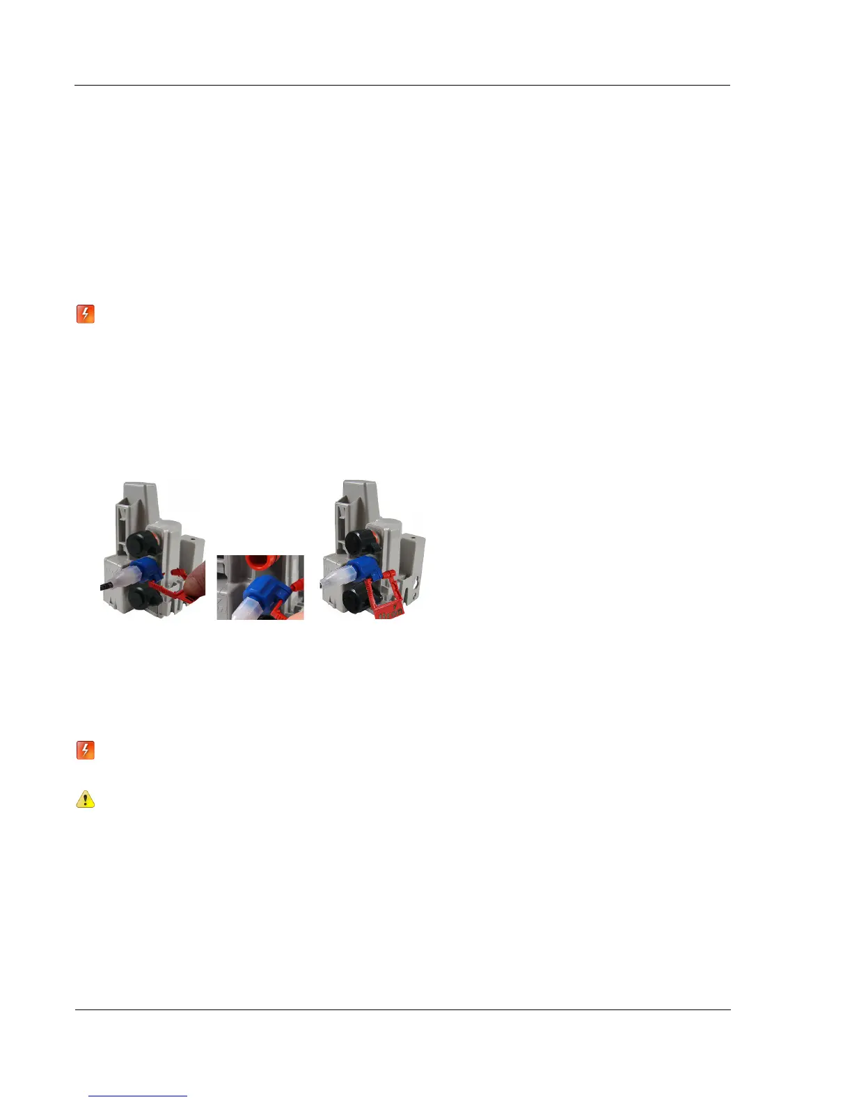
To install a security seal through the protective connector cover
1. Align the protective cover and connector security seal holes.
2. Insert the security seal pointed end through the security holes in the connector and protective cover.
3. Insert the pointed end of the security seal into the cap end and push until the seal locks.
Rod Mount Installation
100W/100W+ and 100WP/100WP+ ERT modules can mount below the pit lid on a customer-supplied 1/2-
inch OD rod. The example installation described in this section uses a fiberglass rod. For more information,
visit www.itron.com and reference the Water Meter Compatibility List (PUB-0063-002).
Warning The rod installation area must be free from other pipes, wires, or facilities that may be
damaged by driving a rod into the ground.
Caution You must follow local codes when using the rod mount installation method. Failure to
use 1/2-inch rod and follow instructions may result in an unreliable installation.
Caution Observe the following guidelines for mounting the 100W/100W+ and 100WP/100WP+
ERT module using the wall mount procedure:
• ERT module positioning other than upright could negatively affect radio
performance and battery life.
•
Use only Itron-approved splice kits or inline connectors.