Initializing, Connecting, and Programming the ERT Module
-0909-006 100W/100W+ and 100WP/100WP+ Datalogging Water ERT Module Installation Guide 13
Proprietary and Confidential
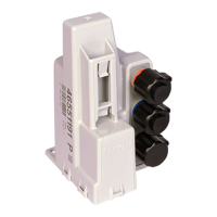
Connecting the 100WP/100WP+ ERT Module to a Remote Meter
Register
Connect the wires from the ERT module to the register according to the following table.
100WP/100WP+ Connections
Register Manufacturer
Red (signal) Black (common) White (tamper)
Register screw color designator
Elster Digital
BLK GRN R
Itron (Actaris) Cyble Sensor (2-
wire)
Either wire Remaining wire must be connected to both ERT module wires
Badger RTR
R BLK Green/bare
Elster V100
BLK R Blue
Sensus PMM
R BLK Bare
Connect the ERT module to the cable using the Itron Splice Kit (see Using the Itron Splice Kit on page 41).
Using an Extension Cable
Order the 25-foot inline connector extension cable assembly (CFG-0151-401) to extend the 100W/100W+
with the inline connector.
Verifying ERT Module Operation
Use one of the following handheld computers to verify consumption:
• FC200SR handheld computer (Itron part number FC2-0005-004 or FC2-0006-004)
• FC300 with SRead
Notes
• Each handheld radio requires special setup and configuration parameters to successfully read and
program 100W/100W+ and 100WP/100WP+ ERT module products. Refer to the respective meter
reading application for specific instructions.
• When comparing the actual register value to that reported by the 100W/100W+ and
100WP/100WP+ ERT module, please keep in mind the ERT module's consumption value is
updated once an hour when it is in a run mode.
Caution Verifying the 100W/100W+ and 100WP/100WP+ ERT module operation requires an
FC200FR or and FC300 handheld computer running FDM v3.2 or higher. Legacy Itron handheld
programming devices cannot read the 100W/100W+ and 100WP/100WP+ ERT modules.