3.3.1 Alignment checks
Initial Alignment (Cold Alignment)
•
Before Grouting Baseplate - To ensure alignment can be obtained
• After Grouting Baseplate - To ensure no changes have occurred during grouting process
• After Connecting Piping - To ensure pipe strains haven’t altered alignment. If changes have occur-
red, alter piping to remove pipe strains on mixer flanges
Final Alignment (Hot Alignment)
After First Run - To obtain correct alignment when both mixer and driver are at operating temperature.
Thereafter, alignment should be checked periodically in accordance with plant operating procedures.
3.3.2 Alignment criteria
Good alignment is achieved when the dial indicator readings as specified in the alignment procedure
are .05 mm (.002 in.) Total Indicated Reading (T.I.R.) or less when the mixer and driver are at operating
temperature (Final Alignment).
During the installation phase, however, it is necessary to set the parallel alignment in the vertical direc-
tion to a different criteria due to differences in expansion rates of the mixer and driver. For Model 3501,
the Cold Setting of Parallel Vertical Alignment table shows recommended preliminary (cold) settings for
electric motor driven mixers based on different pumpage temperatures. Driver manufacturers should be
consulted for recommended cold settings for other types of drivers (steam turbines, engines, etc.).
Table 2: Cold Setting of Parallel Vertical Alignment
Cold Setting of Parallel Vertical Alignment
Fluid Temperature Set Driver Shaft
10°C (50° F) .05 mm (.002 in.) Low
65°C (150°F) .03 mm (.001 in.) High
120°C (250°F) .12 mm (.005 in.) High
3.4 Set up
1.
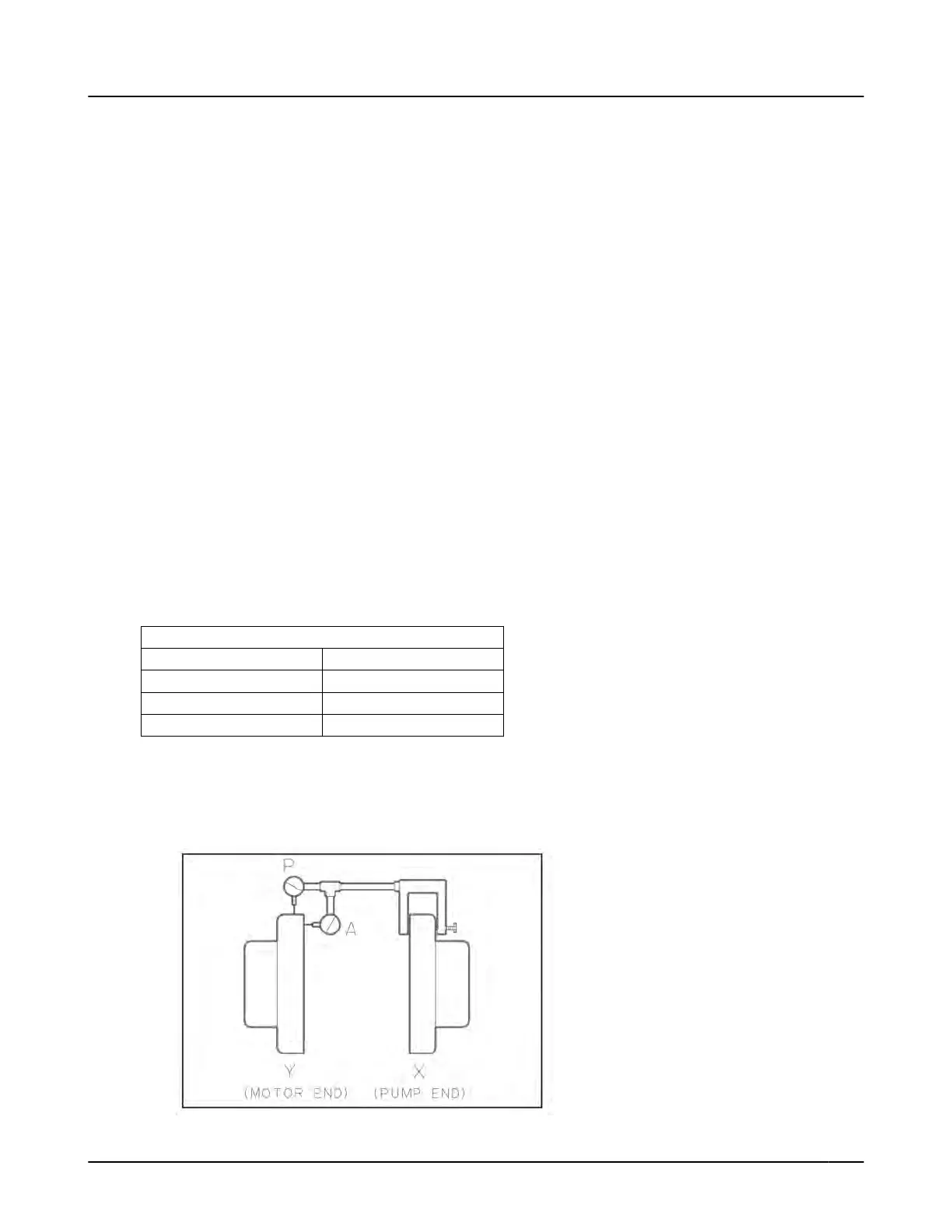
Mount two dial indicators on one of the coupling halves (X) so they contact the other coupling half
(Y), see Figure 11: Dial indicator mounting on page 15.
Figure 11: Dial indicator mounting
3.4 Set up
3501 Installation, Operation, and Maintenance Instructions 15
 Loading...