WARNING:
Seal chambers are heavy
. Use proper support to avoid personal injury.
6.6 Disassembly of bearing frame
1.
Secure bearing frame assembly firmly to a workbench.
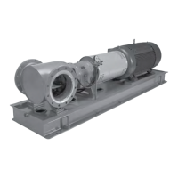
2. Remove coupling hub from shaft (122) by loosening set screw (if provided) and using a puller (Fig.
32).
3. Remove shaft key (400) (Fig. 32).
4. Remove coupling guard end plate by removing bearing housing adjuster screws (370C) (Fig. 32).
5. Remove labyrinth shaft seal assemblies (332A, 333A) from each end of frame (Fig. 32).
Figure 31: Coupling hub and guard end plate
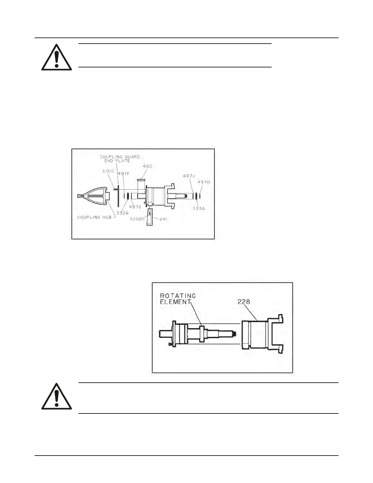
6.
Slide rotating element out of frame (228). If needed, tap rotor end of shaft with a soft blow hammer
to assist in removal (Fig. 33).
Figure 32: Rotating element
WARNING:
Support both ends of shaft to prevent rotating element from dropping when bearings are disen-
gaged from bores.
7. Radial end cover (109A) is installed permanently at factory and should not require removal.
8.
Remove thrust bearing retainer ring (253B) by removing socket head cap screws (236A) (Fig. 34).
6.6 Disassembly of bearing frame
3501 Installation, Operation, and Maintenance Instructions 41
 Loading...