Mini-JLT™ User Manual
4 © 2017 Jackson Labs Technologies, Inc.
Connect a terminal program (TeraTerm is recommended) to the unit via the TTL serial connector
pins on J1, or to the USB serial port, both with 115.2KB 8N1 and no flow-control.
WARNING: Do not connect RS-232 serial levels to connector J1, the unit may get
damaged from RS-232 serial levels on connector J1 as the default configuration is TTL
level.
Both the TTL serial port J1 and the USB port are internally “ored” together, so the user may send and
receive commands to/from both ports as long as commands are not sent to both ports at the same
time. Try some of these SCPI commands:
help?
syst:stat?
GPS?
sync?
meas?
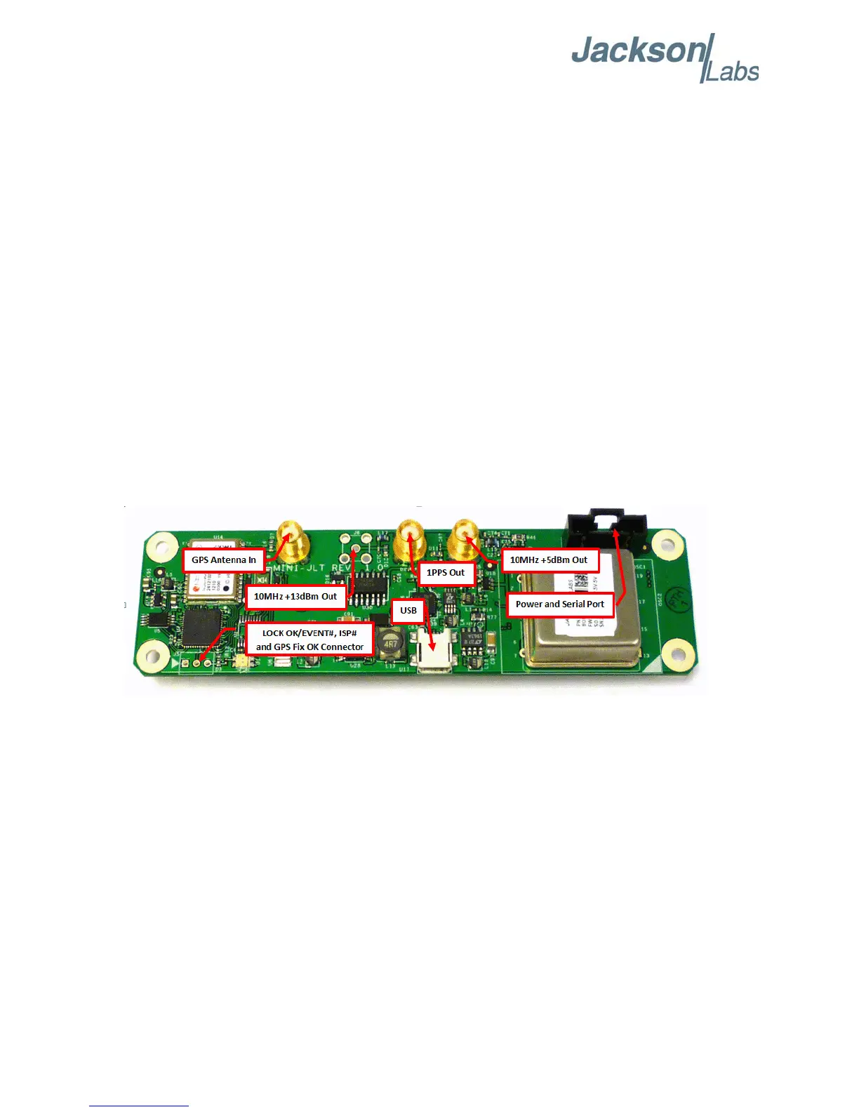
2.1.1 PCB Photos
The Mini-JLT GNSS™ PCB is shown in Figure 2.1.
Figure 2.1 Mini-JLT GNSS™ Single Oven PCB
2.1.2 Mechanical Drawings
The following drawings show the mechanical dimensions and the pinout of the Mini-JLT GNSS™
PCB:
 Loading...