ADpcmcia adapter
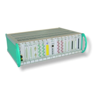
ADwin
30 ADwin Installation, manual version 2.1, December 2005
5.2 Initialization of the hardware
Before you connect your PC to the ADwin system, please read your hardware
manual including the chapter "Initialization of the hardware". Do not connect
any inputs or outputs.
Connecting After you have installed the ADwin system according to the notes in your hard-
ware manual, connect the ADlink cable and power on the ADwin system.
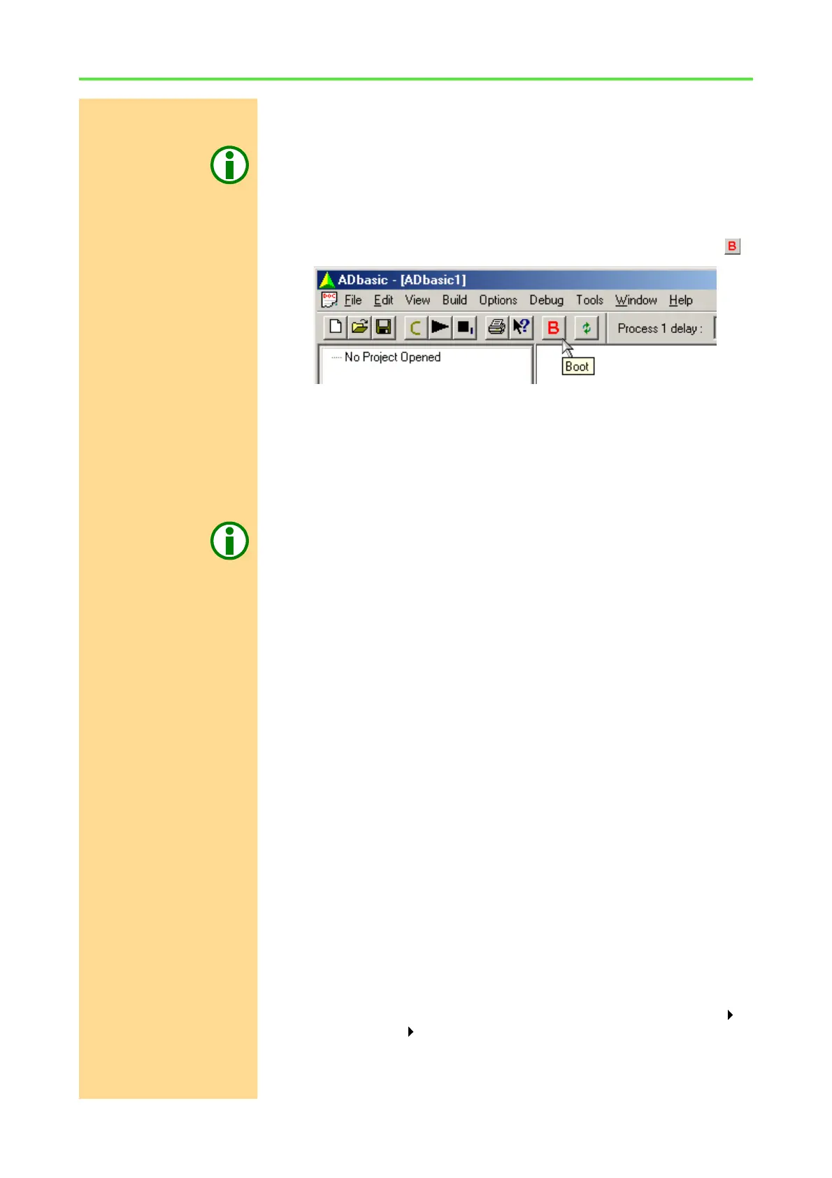
Booting Start ADbasic and boot the ADwin system by clicking on the boot button .
The blinking of the green LED on the ADwin-Gold system or on the CPU mod-
ule of the ADwin-Pro system as well as the display in the status line: "ADwin
is booted" shows that the operating system has been loaded properly and
that ADbasic can access the ADwin system (if not, first check the connections).
Finishing the installation For the further installation please keep to the order of installation instructions
in chapter 2 of this manual:
– For the details about the initialization of your ADwin system, please see
your hardware manual.
Programming with
ADbasic
– The programming of your ADwin system is described in detail in the
ADbasic manual.
– Start programming with the examples in the ADbasic tutorial.
5.3 Connecting several ADwin systems to ISA and PCI
If you want to work only with one ADwin system and the standard base
addresses 150h or 190h, you need not read this chapter.
Operating several ADwin
systems
If you work under the following conditions you should set the hardware
addresses manually to avoid address conflicts:
– Working with several ADwin systems
– Operating systems with ISA and / or PCI interfaces simultaneously
– Operating at least one of the systems with a PCMCIA adapter
An exception is if two ADwin systems are operated with one PCI board, which
has two slots for PCMCIA boards. Here Windows automatically allocates the
address 190h to one of the two boards. Which board it is, you can check in the
text box described above (page 29).
Checking the I/O address
assignment of the
hardware
In any case it is recommended to check first which addresses are already allo-
cated.
– Windows 9x, ME
Call the device manager from the Windows start menu: Settings
Control panel System. Double click the field "Computer" in the
"Device Manager". Under "View Resources" set the display to "In-
put/Output (I/O)".