Page 26
ENGLISH
Jandy
®
Pro Series, Hi-E2
®
and Hi-E2R Gas-Fired Heater
|
Installation & Operation Manual
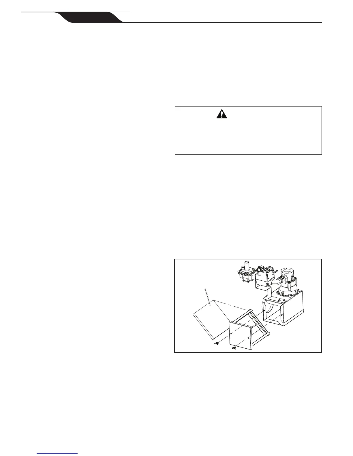
Figure 31. Air lter replacement.
Filter
10. Vent Limit Switch - The vent limit switch
protects the vent system from excessive exhaust
temperature. It is located on the vent diffuser
above the combustion blower. It interrupts burner
operation if temperature becomes too hot for the
plastic materials used to vent the heater.
See the earlier section entitled Start-up and Adjustment
for the normal sequence of operation.
4.4 Combustion Air Filter
WARNING
To avoid the risk of exposure to unsafe levels of
Carbon Monoxide, which can result in serious personal
injury or death, always ensure that the combustion
air filter is properly installed and secured in the tracks
provided in the air filter box.
The combustion air lter is a rectangular foam
lter located in a box near the bottom of the control
compartment. The lter removes lint and large scale dust
particles to prevent blockage of the burner media.
The lter should be replaced annually in normal
service. Heavy use of the heater or operation in adverse
environments may dictate more frequent replacement,
however. It can be removed through the front of the lter
box as illustrated in Figure 31.
Remove the wing nuts retaining the front panel and slide
the panel out. Replace it only with the specied part
available from a Jandy Pro Series representative. Push the
replacement lter into the tracks and slide the panel back in.
3. Temperature Control - The control is an electronic
control which senses water temperature by means
of a thermistor and controls heater operation to
bring the water to that selected. It has two (2)
temperature setting knobs which are typically
used to set pool and spa temperatures. A selector
switch determines which setting is chosen.
4. Ignition Control - The ignition control provides
energy for ignition of the air/gas mixture,
monitors the ame and controls the combustion
blower and gas valve. When the temperature
control requires heat, the ignition control
starts the blower, providing a pre-purge of the
combustion chamber. Then it applies electrical
power to a “hot surface” igniter. When the igniter
is hot enough, it opens the gas valve. It has
sophisticated means to sense ignition and ame
condition so that unburned gas will not escape.
After the burner is shut off, it continues blower
operation to provide a post-purge period.
5. Igniter - The hot surface igniter is a ceramic
element which becomes very hot when electrical
power is applied to it. It functions both as an
igniter and as ame sensor. As a sensor, it is the
electrode through which the ignition control
detects “rectication” of current passed through
the ame. Inadequate rectication indicates an
unsatisfactory ame condition. The ignition
control responds to the ame signal provided by
the ignitor.
6. Venturi Pressure Switch - This switch veries
that air is owing through the combustion system
by sensing pressure reduction at the venturi throat
(relative to pressure at the venturi inlet). It shuts
off the heater if air ow is inadequate.
7. Limit Switches -
Two (2) limit switches prevent
excessive water temperature - both are just outside
of the heat exchanger outlet (slightly before the
mixed water stream). If either senses excessive
temperature, burner operation is interrupted.
8.
Water Pressure Switch - This control senses whether
or not water is available to the heater by measuring
back pressure inside of the heat exchanger. If the
pool water pump fails or the water lter is blocked,
the pressure switch prevents operation of the burner.
It can be affected by the installation conditions as
discussed earlier in this manual.
9. Burner Temperature Limit Switch - This is a
single-use switch which detects abnormal burner
temperature. It is a disc-type switch which is
held against the burner plenum by a sheet metal
bracket. It is not able to be reset. The burner limit
switch prevents or interrupts burner operation if
the burner plenum becomes too hot.