Page 5
ENGLISH
Jandy
®
Pro Series, Hi-E2
®
and Hi-E2R Gas-Fired Heater
|
Installation & Operation Manual
WARNING
To Reduce the Risk of Fire, install pool equipment in an
area where leaves or other debris will not collect on or
around the equipment. Keep surrounding area clear of
all debris such as paper, leaves, pine-needles and other
combustible materials.
2.2 Heater Assembly and Preparation
The Hi-E2 can be installed in a variety of ways, some of them
requiring preparation or assembly in the eld. In all cases,
condensate tubing and ttings, which are provided with the
heater, must be connected and routed. Water connections are
provided on the right side of the heater but can be changed to
the left side by reversal of the water headers.
It is best to handle these preparations before the heater
is in its nal location. Instructions are provided in
subsequent sections of this document.
Installation at High Elevation
The Hi-E
2 has a venturi-type combustion system which
does not require modication for operation at high
elevation. In this type of system, air and fuel gas density
changes are automatically compensated for, assuring
proper air/fuel mixture. Heating capacity is reduced about
3 percent per 1000 feet (305 meters) above sea level. In
general, efciency at high elevation is equal to or better
than at sea level.
2.3 Heater Location
The Hi-E2 may be installed indoors or outdoors as outlined
in later sections. When installed indoors, combustion
air will often be piped to the heater and this requirement
may affect the choice of location, see later section on air
for combustion and ventilation. Both indoor and outdoor
installations require provision of means for disposal of
combustion condensate per section 2.8.
Install the heater at least 5 feet (1.52 meters) from the
inside wall of the pool or spa unless the heater is separated
from the pool or spa by a ve-foot (1.52 meter) high solid
fence, wall or other permanent barrier.
Equipment must be installed on a rm, solid, non-
absorbent level surface; and per the requirements of
local codes and Authority Having Jurisdiction (AHJ).
Equipment can weigh up to 300 lbs. Use suitably rated
mounting surface materials to avoid risk of settlement,
and never use sand to level the equipment as the sand
will wash away. Check local building codes for additional
requirements.
CAUTION
When pool equipment is located below the pool
surface, a leak from any component can cause large
scale water loss or flooding. Zodiac Pool Systems, Inc.
cannot be responsible for such water loss or flooding
or resulting damage.
When pool equipment is located below the pool surface,
a leak from any component can cause large scale water
loss or ooding. Zodiac Pool Systems, Inc. cannot be
responsible for such water loss or ooding or resulting
damage. Location of the heater below or above the pool
deck affects operation of its water pressure switch. See
sections on water piping and heater start-up for more
information about this.
Locate the heater in an area where water leakage will
not result in damage to the area around the appliance or
to a structure. If forced to locate the heater where water
leakage may cause damage, provide a suitable pan with
drain under the heater. This pan must not restrict air ow
or heater functions.
In selection of a location, disposal of combustion
condensate must also be considered. The heater can
produce three gallons of condensate water per hour
under some operating conditions. Means to drain this
condensate must be available or special provisions, such
as a condensate pump must be provided. See later section
on condensate disposal.
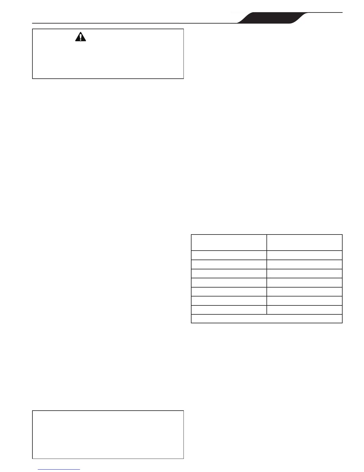
2.4 Installation Clearances
Clearances between the heater and combustible material
must be per Table 1.
Table 1. Installation Clearance Requirements.
Surface/Component Minimum Clearance
Inches (mm)
Rear & Blank Side 2 (55)
Piping Side 12 (305)
Front 18 (455)*
Top - Indoors 6 (150)
Top - Outdoors Open (See Note)
Flooring Combustible
Vent 0
* For Canada 24 inches (610 mm) clearance
NOTE See Section 2.5 for outdoor installation requirements.
These clearances are the minimum acceptable. Whenever
possible, larger clearances should be provided to assure
adequate room for service operations. Note that gas piping
must be provided through the left side of the unit and
that the combustion air duct, when provided, also enters
through the left side. See later section on combustion air,
and also the section on water piping.
Do not install the heater on carpeting or similar material.
2.5 Outdoor Installation
Locate the heater in an open, unroofed area and maintain
the clearances shown in Table 1. Do not locate the heater
below or adjacent to any doors, windows, louvers or
grates, etc., which connect in any way with an inhabited
area of a building, even through another building such as