Page 31
ENGLISH
Jandy
®
Pro Series, Hi-E2
®
and Hi-E2R Gas-Fired Heater
|
Installation & Operation Manual
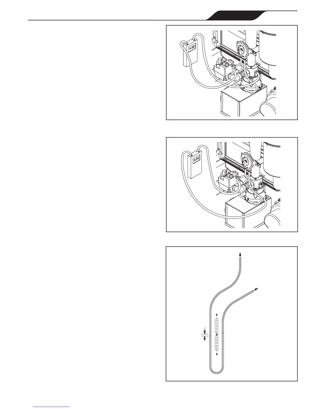
Figure 34. Gas orice differential measurement.
-
+
Figure 36. Gas pressure offset measurement with
U-tube manometer.
To Venturi
Inlet Service
Port
To Gas Valve
Service Port
0.2" WC
Figure 35. Gas pressure offset measurement.
+
-
4.6.3 Air Flow Investigation
If gas pressure offset is correctly set but gas orice
differential is abnormal, check air ow through the system
per the following sections.
4.6.3.1. Unred Venturi Differential
Pressure.
Determine if air ow through the system is in a normal
range by operating the system with the gas valve turned
off. Connect the positive side of the manometer to the
venturi inlet service port, which is at the bottom on the
right side. Connect the negative side of the manometer
to the gas valve service port of the gas valve, see Figure
37. Turn the gas valve knob to "Off". Turn the heater
on by selecting "Pool" or "Spa" at the control and
adjusting the temperature setting high. The blower will
start immediately and the manometer will indicate the
"unred venturi differential" pressure. This is the pressure
difference created by airow through the venturi. It should
be approximately 4.7" ± 0.3" at sea level. See Section
4.6.5 for other elevations.
Note that when the heater is operated with the gas valve
off, it will eventually “lock out” because the ignition
control does not sense ame. Normally there will be
enough time to obtain the measurement, but if necessary,
additional blower operation can be induced by turning the
Flex-Temp control off and then back on again.
If the reading is not normal, attempt to correct it by
blower speed adjustment. Blower speed is adjusted by
turning a special screw on the right side of the motor - at
about 4 o’clock, see Figure 38. A small countersunk hole
is provided there for access to the screw, but is covered by
a thin silver-colored label. Remove or puncture the label.
A small at-blade screw driver is required. It must have
a 3/32” or 2.5 mm (.098”) blade and must be about
4-1/2” long. A jeweler’s screw driver or an electronics
pot adjustment screw driver (with handle cut short if
necessary) can be used. Insert the screw driver through
the hole on the motor housing. Turn it clockwise to
increase the ow and counter-clockwise to decrease.
If blower speed adjustment results in acceptable venturi
differential, shut off the system at the Flex-Temp control
and return to “Gas orice differential” measurement
per Section 4.6.2.2. Make a nal speed adjustment as
necessary to obtain correct gas orice differential.
If the system cannot be made to operate normally by
blower speed adjustment, investigate possible ow
problems per the following sections.